OptidriveODP‐2UserGuideRevision1.30
www.invertekdrives.com
23
4 ElectricalInstallation
4.10.4. “STO“Operation
Whenthe“STO”inputsareenergised,the“STO”functionisinastandbystate,ifthedriveisthengivena“Startsignal/command”(asperthe
startsourcemethodselectedinP1‐13)thenthedrivewillstartandoperatenormally.
Whenthe“STO”inputsarede‐energisedthentheSTOFunct
ionisactivatedandstopsthedrive(Motorwillcoast),thedriveisnowin“Safe
TorqueOff”mode.
Togetthedriveoutof“SafeTorqueOff”modethenany“Faultmessages”needtoberesetandthedrive“STO”inputneedstobere‐energised.
4.10.5. “STO”StatusandMonitoring
Thereareanumberofmethodsformonitoringthestatusofthe“STO”input,thesearedetailedbelow:
DriveDisplay
InNormaldriveoperation(MainsACpowerapplied),whenthedrives“STO”inputisde‐energised(“STO”Functionactivated)thedrivewill
highlightthisbydisplaying“InHibit”,(Note:Ifthedriveisinatri
ppedconditionthentherelevanttripwillbedisplayedandnot“InHibit”).
DriveOutputRelay
• Driverelay1:SettingP 2‐15toavalueof“13”willresultinrelayopeningwhenthe“STO”functionisactivated.
• Driverelay2:SettingP 2‐18toava
lueof“13”willresultinrelayopeningwhenthe“STO”functionisactivated.
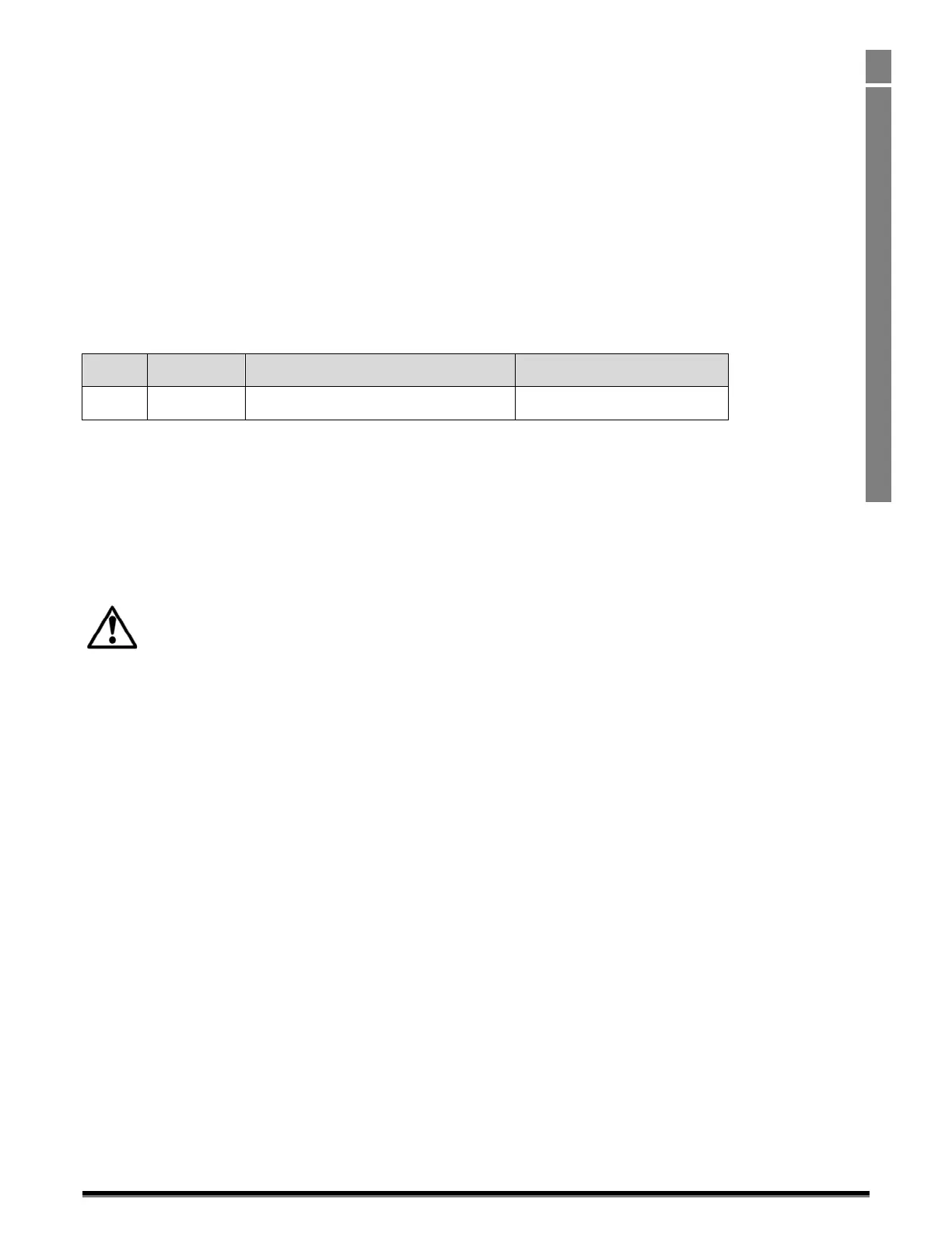
“STO”FaultCodes
Fault
Code
Code
Number
Description CorrectiveAction
“Sto‐F”
29
Afaulthasbeendetectedwithineitherofthe
internalchannelsofthe“STO”circuit.
RefertoyourInvertekSalesPartner
4.10.6. “STO”Functionresponsetime
Thetotalresponsetimeisthetimefromasafetyrelatedeventoccurringtothecomponents(sumof)withinthesystemrespondingand
becomingsafe.(StopCategory0inaccordancewithIEC60204‐1)
• Theresponsetimefromthe“STO”inputsbeingde‐energisedtotheoutputofthedrivebe
inginastatethatwillnotproducetorquein
themotor(“STO”active)islessthan1ms.
• Theresponsetimefromthe“STO”inputsbeingde‐energisedtothe“STO”monitoringstatuschangingstateislessthan20ms
• TheresponsetimefromthedrivesensingafaultintheST
Ocircuittothedrivedisplayingthefaultonthedisplay/Digitaloutput
showingdrivenothealthyislessthan20ms.
4.10.7. “STO“ElectricalInstallation
The“STO”wiringshallbeprotectedfrominadvertentshortcircuitsortamperingwhichcouldleadtofailureofthe“STO”input
signal,furtherguidanceisgiveninthediagramsbelow.
Inadditiontothewiringguidelinesforthe“STO”circuitbelow,section4.1.1“RecommendedinstallationforEMCcompliance.shouldalsobe
f
ollowed.
Thedriveshouldbewiredasillustratedbelow;the24Vdcsignalsourceappliedtothe“STO”inputcanbeeitherfromthe24Vdconthedriveor
fromanExternal24Vdcpowersupply.
 Loading...

