OptidriveODP‐2UserGuideRevisions1.30
24
www.invertekdrives.com
4ElectricalInstallation
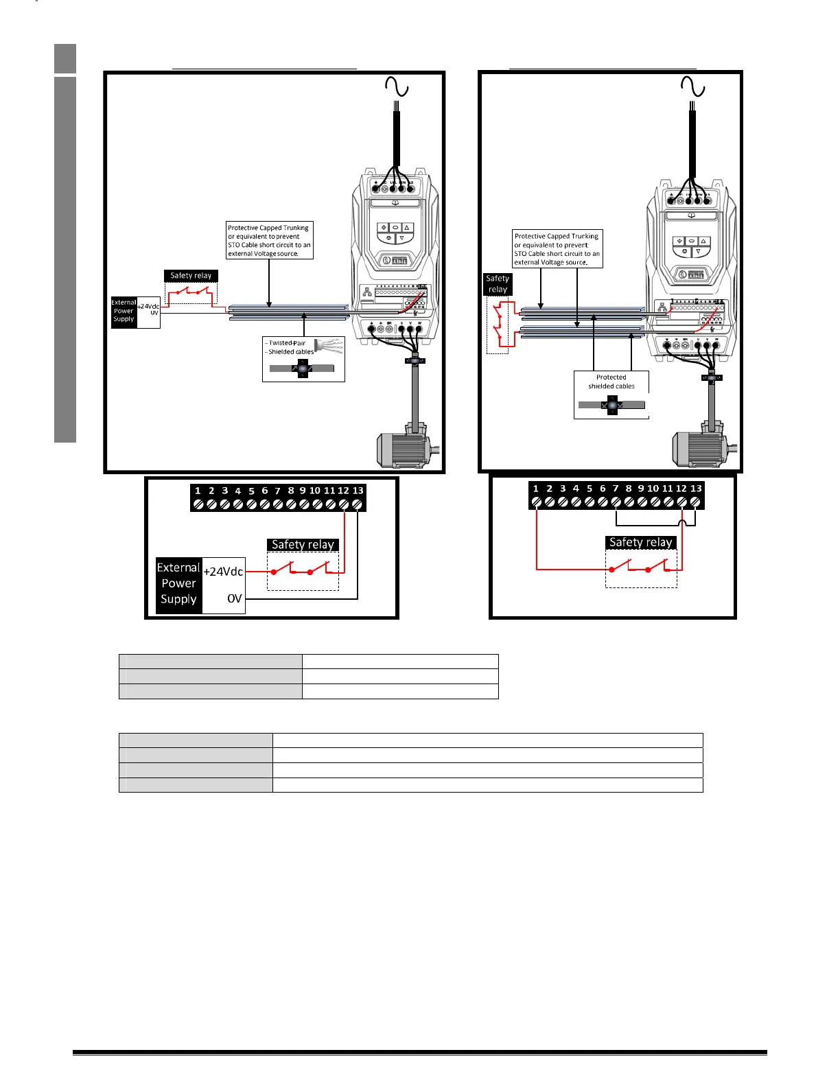
4.10.7.1. Recommended“STO”wiring
UsinganExternal24VdcPowerSupply. Usingthedriveson‐board24Vdcsupply
Note:TheMaximumcablelengthfromVoltagesourcetothedriveterminalsshouldnotexceed25mtrs.
4.10.8. ExternalPowersupplySpecification.
VoltageRating(Nominal) 24Vdc
STOLogicHigh 18‐30Vdc(Safetorqueoffinstandby)
CurrentConsumption(Maximum) 100mA
4.10.9. SafetyRelaySpecification.
Thesafetyrelayshouldbechosensothatatminimumitmeetsthesafetystandardsinwhichthedrivemeets.
StandardRequirements SIL2orPLdSC3orbetter(WithForciblyguidedContacts)
NumberofOutputContacts 2independent
SwitchingVoltageRating 30Vdc
SwitchingCurrent 100mA
4.10.10. Enablingthe“STO”Function
The“STO”functionisalwaysenabledinthedriveregardlessofoperatingmodeorparameterchangesmadebytheuser.
4.10.1. Testingthe“STO”Function
Beforecommissioningthesystemthe“STO”functionshouldalwaysbetestedforcorrectoperation,thisshouldincludethefollowingtests:
• Withthemotoratstandstill,andastopcommandgiventothedrive(asperthestartsourcemethodselectedinP1‐13):
o De‐energisethe“STO”inputs(Drivewilldisplay““InHibit”).
o Giveastartcommand(asperthestartsourcemethodselectedinP1‐13)andcheckthatth
edrivestilldisplays“Inhibit”and
thattheoperationisinlinewiththesection4.10.4andsection4.10.5“STO”StatusandMonitoring
• Withthemotorrunningnormally(fromthedrive):
o De‐energisethe“STO”inputs
o Checkthatthedrivedisplays“InHibit”andthatthemotorsto
psandthattheoperationisinlinewiththesectionand
section
Wiresshouldbe
protected
againstshort
circuitsas
shownabove
 Loading...

