CHV180 series frequency inverter special for elevator Appendix A
.121.
P1.22
P1.21Emergency speed
P1.22
OFF
FWD
v
t
EMER
ON
ON
ON
ON
ON
ON
OFF
OFF
OFF
OFF
OFF
OFF
KM3
KM
ON
OFF
OFF
ON
ON
T3T2
T1
T5
T6
T7
T8
T0
T4
FC
TC
FB
TB
Y1
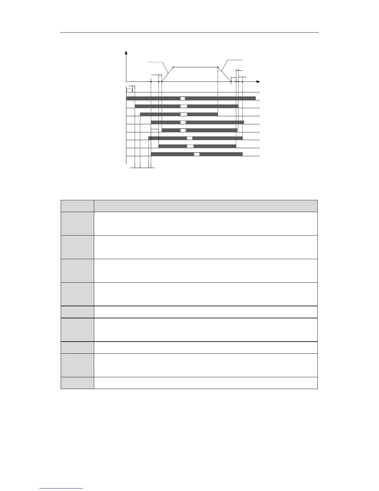
Figure A.7 Sequence chart of emergency run.
The meanings of T0~T8 are as follows:
Symbol
emergency power is on
T1
The time is the delay time from the controller output emergency command
to output run command
T2
The time is the system delay time from inverter received running signal to
output actuates command of contactor.
T3
The time is the wait delay time form inverter output contactor actuates
command to receive contactor feedback signal.
T4 P8.06(Contacting brake close delay time)
T5
The time is the wait delay time form inverter brake-releasing output
command to receive contracting brake feedback signal.
T6 P8.05(Contacting brake open delay time)
T7
The time is the wait delay time from inverter output closed-brake
command to receive stopping command of external control.
T8 P8.20(Inverter stop delay time)
When the main power is off, the controller cut off main power relay (KM1), after
T0, the control switch of emergency power will be closed, and output emergency
command at the same time , after T1, the inverter receive running command
from controller, then after T2, the inverter output actuate command to contactor.
After T3, the inverter received the feedback signal from contactor, then the
 Loading...