Goodrive100-PV series solar pumping inverters Keypad operation procedure
-16-
4 Keypad operation procedure
4.1 Keypad introduction
Keypads are used to control GD100-PV series inverters, read the state data and adjust
parameters. If external keypads are needed, select keypad extension wires.
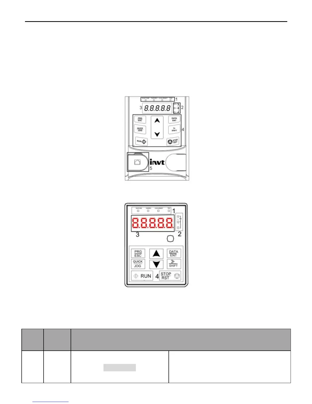
Figure 4-1 Keypad diagram for inverters ≤ 2.2kW
Figure 4-2 Keypad diagram for inverters ≥ 4kW
Note: External keypads can be configured for inverters ≤ 2.2kW. The keypads of inverters ≥
4kW can be used as external keypads.
LED off means that the inverter is in the
stopping state; LED blinking means the
inverter is in the parameter autotune state;

 Loading...