Goodrive200A inverters Function parameters
58
Function
code
Name Detailed instruction of parameters
Default
value
11:Lower limit frequency arrival
12:Ready for operation
13:Pre-magnetizing
14:Overload pre-alarm
15: Underload pre-alarm
16:Completion of simple PLC step
17:Completion of simple PLC cycle
18:Setting count value arrival
19:Defined count value arrival
20:External fault valid
21:Length arrival
22:Running time arrival
23:MODBUS communication virtual terminals
output
26: DC bus voltage establishment
27: Auxiliary motor 1
28: Auxiliary motor 2
P06.05
Polarity
selection of
output
terminals
The function code is used to set the pole of the
output terminal.
When the current bit is set to 0, input terminal is
positive.
When the current bit is set to 1, input terminal is
negative.
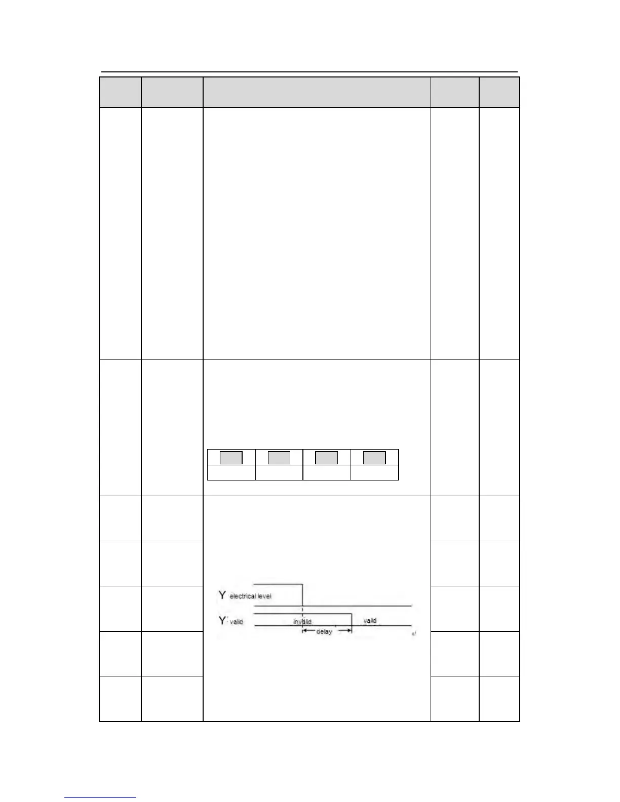
BIT0 BIT1 BIT2 BIT3
Y HDO RO1 RO2
Setting range:0~F
0 ○
P06.06
Y1
switching-on
delay time
The function code defines the corresponding
delay time of the electrical level change during
the programmable terminal switching on and off.
The setting range :0.000~50.000s
Note: P06.08 and P06.09 are valid only when
P06.00=1.
0.000s
Y1
switching-off
delay time
HDO
switching-on
delay time
HDO
switching-off
delay time
RO1
switching-on
delay time

 Loading...


