Goodrive18 series two-in-one VFD Function parameters and function terminal reuse
-49-
load
1: Multi-points V/F curve
2: Torque step-down V/F curve (1.3 order)
3: Torque step-down V/F curve (1.7 order)
4: Torque step-down V/F curve (2.0 order)
Curves 2 – 4 apply to the torque loads such as
fans and water pumps. You can adjust according
to the characteristics of the loads to achieve best
performance.
5: Customized V/F (V/F separation); in this
mode, V can be separated from f and f can be
adjusted through the frequency given channel
set by P00.06 or the voltage given channel set
by P04.27 to change the characteristics of the
curve.
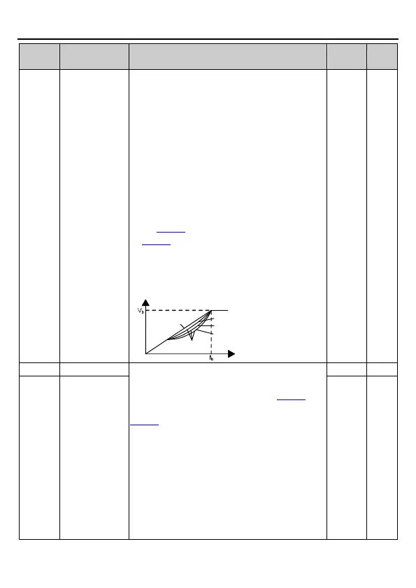
Note: In the following figure, V
b
is the motor
rated voltage and f
b
is the motor rated frequency.
Output voltage
Output frequency
Linear type
Square type
Torque step-down V/F curve (1.3 order)
Torque step-down V/F curve (1.7 order)
Torque step-down V/F curve (2.0 order)
In order to compensate for low-frequency torque
characteristics, you can make some boost
compensation to the output voltage. P04.01 is
relative to the maximum output voltage V
b
.
P04.02 defines the percentage of cut-off
frequency of manual torque boost to the rated
motor frequency f
b
. Torque boost can improve
the low-frequency torque characteristics of
SVPWM.
You should select torque boost based on the
load. For example, larger load requires larger
torque boost, however, if the torque boost is too
large, the motor will run at over-excitation, which
will cause increased output current and motor

 Loading...