INVT iMars MG series grid-tied solar inverters Display panel
5.1 LED indicators
There are three LED indicators on the panel:
(1) “Run”, operation indicator, green;
(2) “Warn” recoverable fault indicator, yellow;
(3) “Fault”, unrecoverable fault indicator, red.
The inverter state includes 6 states of stand-by, self-inspection, power generation, recoverable
fault and unrecoverable fault; LED indicators are on, off and blinking. Please refer to table 5-1 for
detailed state of inverter and LED indicators state.
“
”: LED indicator is off;
“
” (green), “ ” (yellow), “ ” (red): LED indicator is blinking at every 0.25S or 0.5S;
“
(Green), “ ” (yellow), “ ” (red): LED indicator is on.
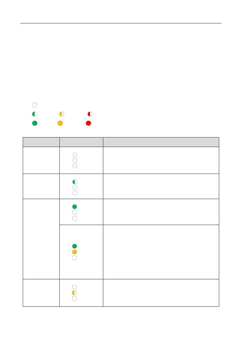
Table 5-1 Inverter state and LED indicators
Inverter state LED indicators Description
Stand-by
No power on. All indicators off.
Self-inspection
Green indicator blinks in every 0.25s, others off.
Power on and ready for self-inspection
Power
generation
Green indicator keeps on, others off.
Grid-tied power generation.
(1) Grid-tied power generation, but clock fault (A007);
(2) Grid-tied power generation, but DC input fault
(A001 or E001);
(3) Grid-tied power generation,but fan fault(E006 or
E012);
Green and yellow indicator keeps on, others off.
Recoverable
fault
Inverter stand-by. The public grid fault(A001, A003,
A004, A005or A006);
Yellow indicator blinks in every 0.5s, others off
- 33 -
 Loading...