PRODUCT DESCRIPTION | IPG PHOTONICS
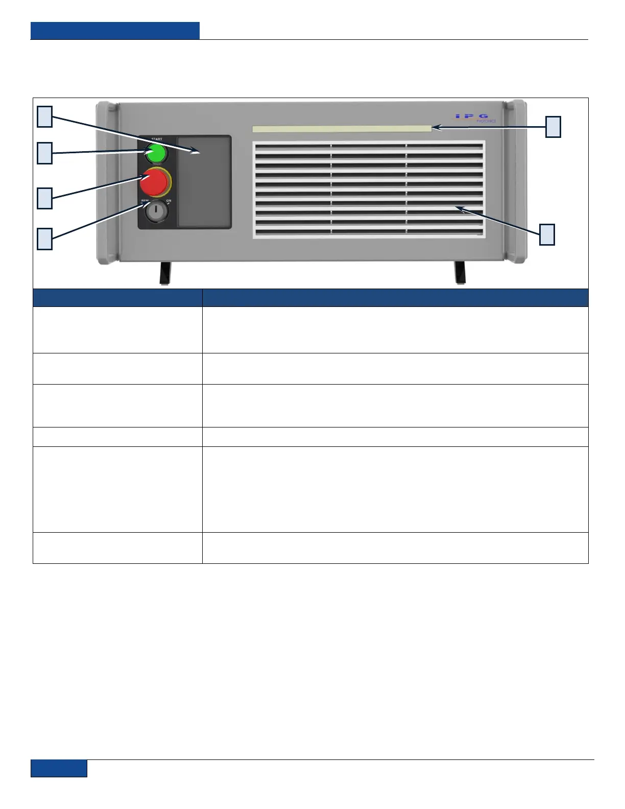
Front Panel View
Figure 5: Front Panel Layout
3-position key switch controls the laser operation mode:
Left position – Remote mode, Central position – laser Off, Right position – Local mode.
Note: The key cannot be removed in the Remote or Local mode positions.
Temporarily suspends power to the laser module. When active, main DC power supply
is disabled. (Reset by turning clockwise or pulling out).
3. Start Button w/Indicator
When pressed, turns ON the internal main power supply of the laser assuming that the
POWER key is in the LOCAL position. When the indicator is “ON” the internal power
supply is active and the laser is capable of producing laser radiation.
Is used to set device settings and to display measured parameters and alarm messages.
LOCAL Mode:
The indicator will blink for a short period after emission is enabled and before laser
radiation is emitted. Once laser emission is “ON”, the indicator will be steady state “ON.”
REMOTE Mode:
The indicator is lit as soon as emission is enabled.
This is removed by pulling on each side to access the filter element (refer to Table 18:
Replacement Parts).


 To Next Page