IPG PHOTONICS | USING YOUR DEVICE
T
T
Y
Y
P
P
I
I
C
C
A
A
L
L
R
R
E
E
S
S
P
P
O
O
N
N
S
S
E
E
T
T
I
I
M
M
E
E
Direct connection to E-Stop push-
button on the front panel. If E-Stop on
the front panel is pressed, channels 3
and 4 are open.
A high condition indicates that the
internal main power supply is active.
A high condition indicates that the
internal main power supply is active.
Return for signals on pins 5, 6.
Return for signals on pins 5, 6.
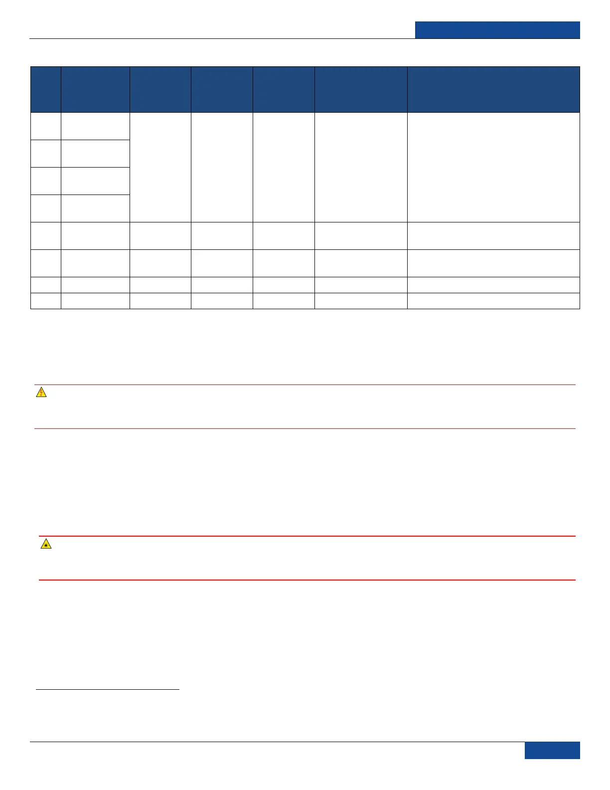
Table 5: 8-pin Connector Pinout
Initial Power-up Sequence
Power-up Sequence
WARNING: All electrical connections (and water connections for water-cooled models) must be
connected prior to applying power to the unit. In addition and where applicable, all connections
must be secured with screws to ensure proper functionality.
1. Ensure that the AC power is removed and the E-Stop button on the front panel is pushed in.
2. Inspect the optical output end face to check for dust and debris (refer to the Optical Fiber Connector
Inspection and Cleaning Guide section for more information).
3. Properly align the output fiber into the delivery optics.
4. Properly secure optical output collimator.
WARNING: NEVER look directly into a live fiber and make sure that you wear appropriate laser
safety eyewear at all times while operating the product. Make sure all power is removed from the
laser when handling the delivery cable.
5. Make sure the interlock (pins 1 to 4, 2 to 3) on the interface connector is closed.
6. Release (pull out) the E-Stop button on the front panel and ensure that the external E-Stop (from
the 24-pin connector) is disengaged if used.
7. Ensure that the air-cooling vents are unobstructed to allow proper cooling of the device. Verify that
the external cooling unit is powered on (for water-cooled models).
1
Interlock response time (500 ms under normal conditions) must be additionally considered to ensure the safe state of the device.
 Loading...