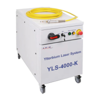
3. Place fiber connector in the holder of the microscope and then place pressure on the center of the
securing arm before tightening the locking screw (Figure 15).
Figure 15: Fiber Connector Mounted on IPG Microscope
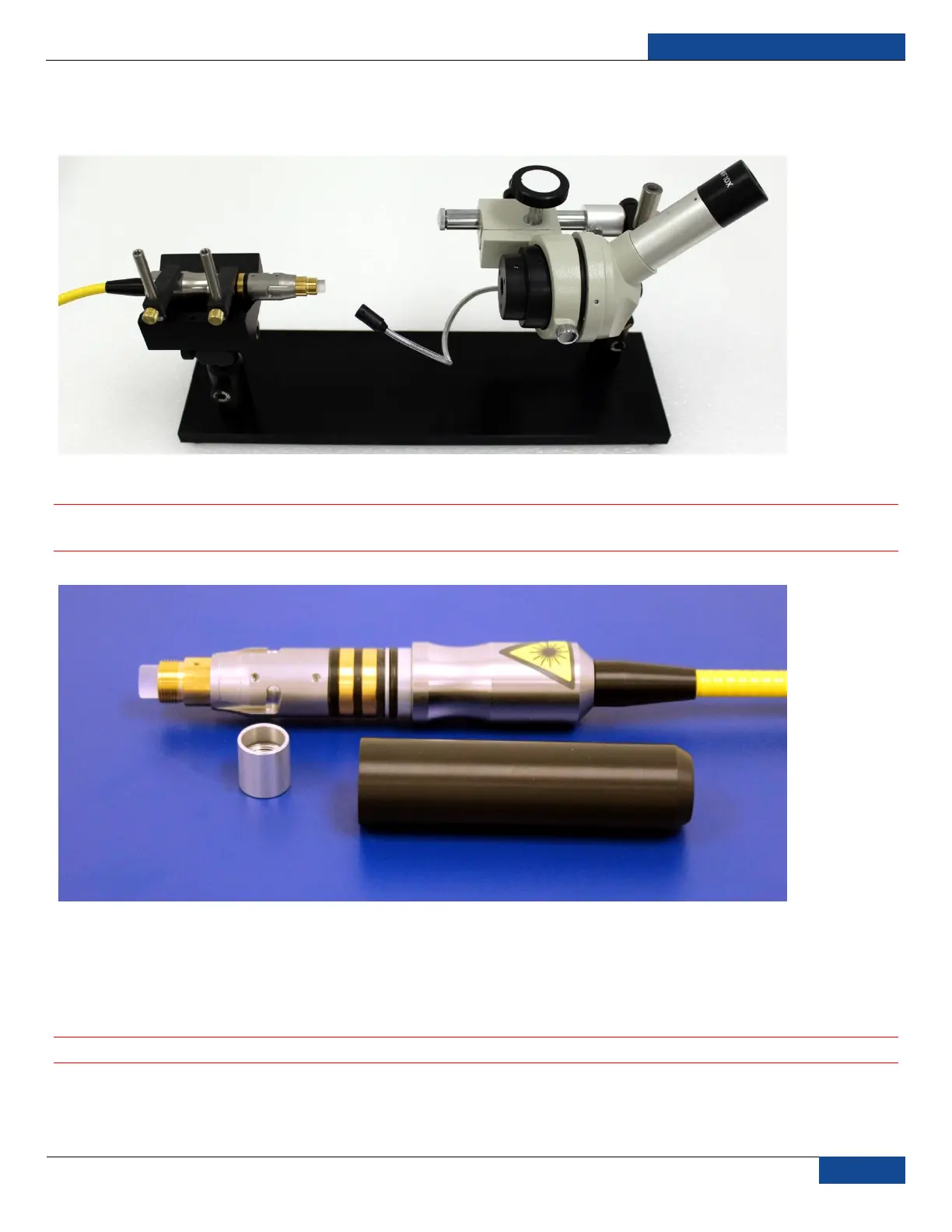
4. Remove cap and sleeve from connector (Figure 16).
IMPORTANT: Place the cap face down on a clean surface. Placing the cap face down on a lint free
wipe is the best choice if the surfaces are questionable.
Figure 16: Fiber Cap and Sleeve Removed
5. Focus the microscope onto the connector surface.
6. Use light source to illuminate the face of the connector so that the light is reflected from the surface
of the microscope. This is achieved if you see a bright golden shine from the IPG (yellow cable)
connector end-face or a blue surface for the connector (Figure 19).
IMPORTANT: Always look at the surface at a slight angle to improve visibility.
7. Inspect the surface carefully. Any contamination will lead to dark spots on the surface and eventual
fiber failure (see Figure 19 for examples). If contamination is visible on the quartz block, continue to
the next step. Proceed to Step 14 if there is no contamination visible.
 Loading...