EasyManua.ls Logo

IPG YLR Series - Pulse Editing; Sketching and Modifying Pulses

IPG YLR Series
102 pages
Print Icon
To Next Page IconTo Next Page
To Previous Page IconTo Previous Page
Loading...
YLR-SERIES USER GUIDE
50
C
C
O
O
D
D
E
E
D
D
E
E
S
S
C
C
R
R
I
I
P
P
T
T
I
I
O
O
N
N
E
E
X
X
A
A
M
M
P
P
L
L
E
E
S
S
STA
(cont.)
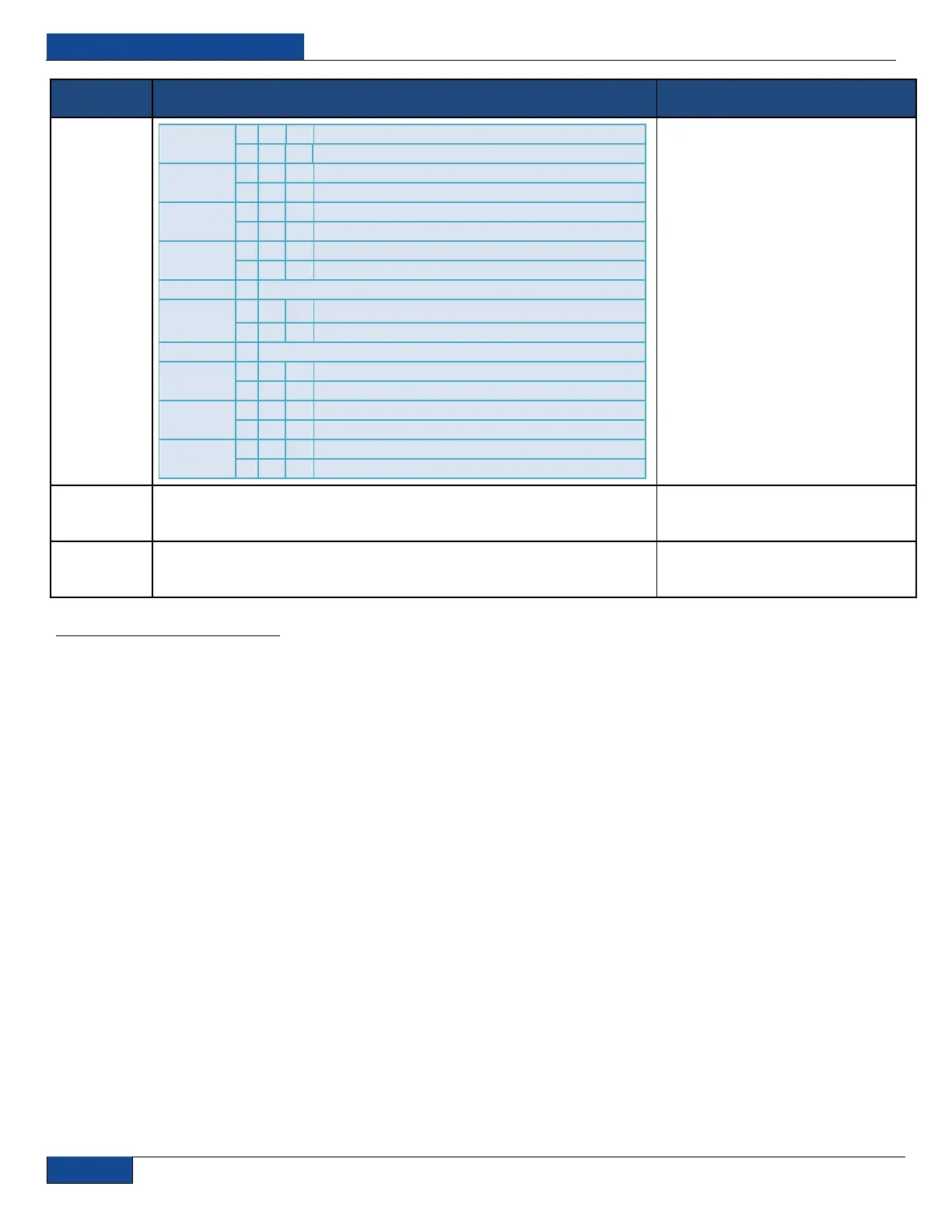
Bit 22
1
-
0
=
Waveform Pulse Mode Disabled
-
1
=
Waveform Pulse Mode Enabled
Bit 23
2
-
0
=
Normal operation
-
1
=
High Duty Cycle
Bit 24
-
0
=
Normal operation
-
1
=
Low Temperature
Bit 25
-
0
=
Power Supply OK
-
1
=
Power Supply Failure 2
Bit 26
-
Reserved
Bit 27
-
0
=
Hardware Aiming Beam Control Disabled
-
1
=
Hardware Aiming Beam Control Enabled
Bit 28
-
Reserved
Bit 29
-
0
=
Normal operation
-
1
=
Critical Error
Bit 30
-
0
=
Optical Interlock OK
-
1
=
Optical Interlock active
Bit 31
-
0
=
Normal Operation
-
1
=
Average Power too High
SIP
Set IP – Followed by a number in dot-decimal notation sets
the IP address for the laser.
Sent: “SIP 10.0.0.2”
Response: “SIP: 10.0.0.2”
UFP
Unlock Front Panel – Unlocks touch-screen display on the
front panel of the laser.
Sent: “UFP”
Response: “UFP”
Table 9: Interface Commands
1
Models with Pulse Shaping Option Only
2
QCW Models Only

Table of Contents