IPG PHOTONICS | PRODUCT DESCRIPTION
Rear Panel View
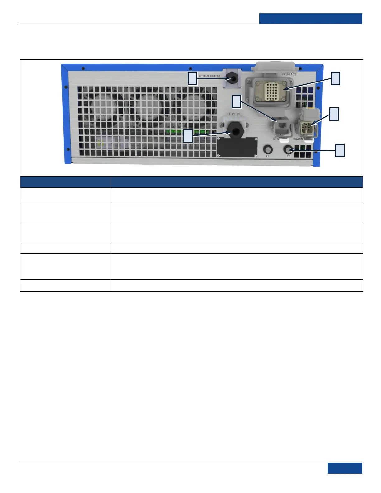
Figure 6: Rear Panel Layout
1. Laser Output
(fiber removed)
The output of the laser (fiber cable) is delivered through this location.
2. Hardwiring Interface
(24-pin)
24-pin connector provides digital interface or hardwiring control of the laser. See Table 4: 24-
pin Connector Pinout for detailed information.
3. Hardwiring Interface
(8-pin)
8-pin connector provides status of the Power Supply and E-Stop. See Table 5: 8-pin Connector
Pinout for detailed information.
3-pin screw terminal connector for AC input wiring. Refer to the SPECIFICATION YTTERBIUM
FIBER LASER document included with this product to determine your models power
requirement.
Replaceable fuses F1, F2 (refer to Table 18: Replacement Parts)
Optical Output Fiber Terminations
Machines with a Connector
The end connector of the fiber (Figure 7) utilizes a protective cap that covers and protects the optical
surface and electrical pins of the safety systems within the process fiber when not in use. These protective
caps must be removed from the connectors when connecting the process fiber cable of the laser to an
optical head. The protective caps should only be removed from the connectors immediately before optical
cleaning and mounting in an adapter.


 To Next Page