ASSEMBLY & PRE-DELIVERY INSPECTION
number plate and
damp on the
. Install and secure the upper
. Front Bumper - Install front bumper and secure with
our bolts supplied in sundr
box.
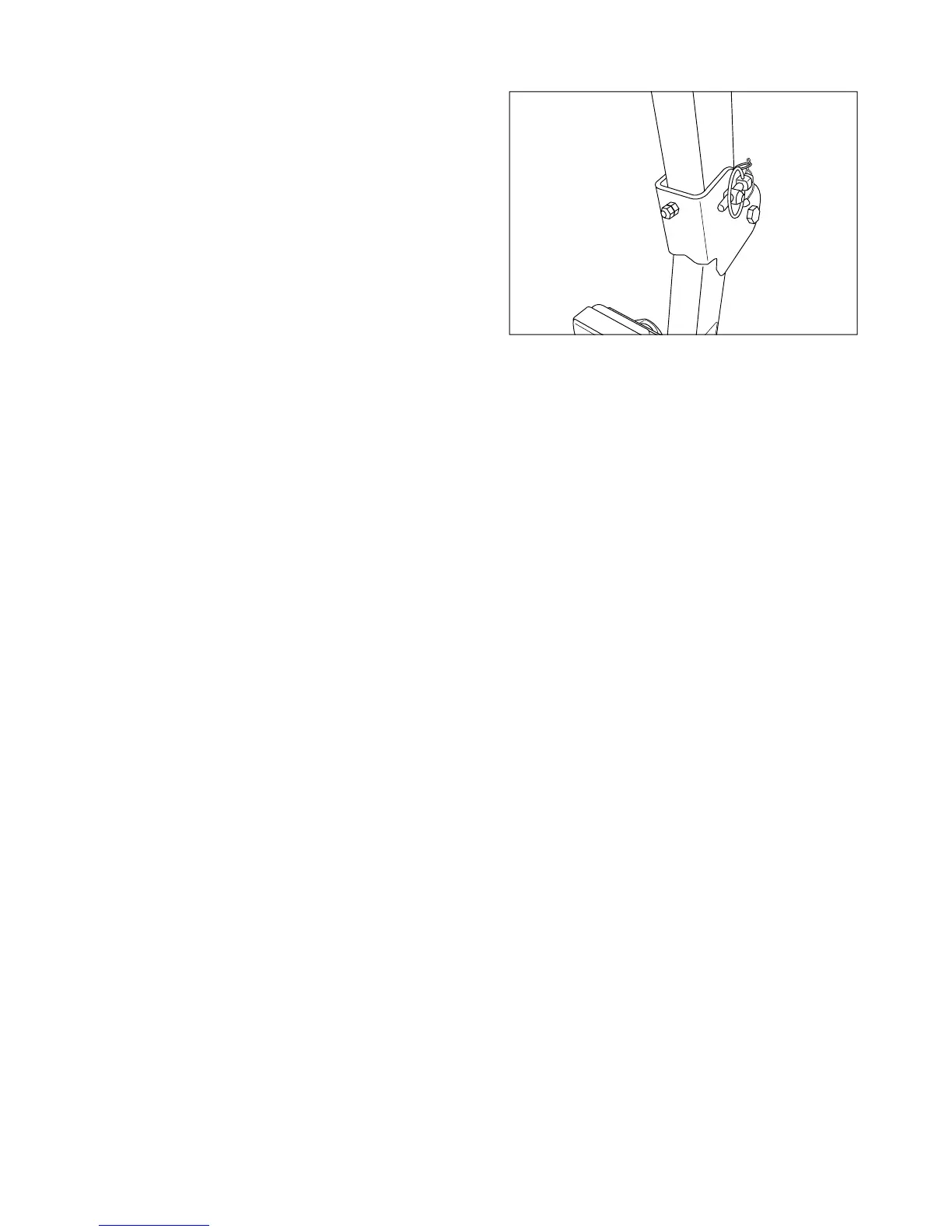
7. Install the rear view mirror. Position of mirror
ht, attach electrical connectors to
onnectors located at fender and R
eat - Remove bolts from seat frame and install
same hardware.
If it is required to equip the seat belt, please ask
. Three-Point Hitch - Three-point hitch is partiall
embled, with lift links attached at the top to the lift
chains attached to the lower links.
a. Attach lower links to Tractor attachin
nch pins. Lower links will flare
out ward t rear and retainin
onnect clevis end of check chains to axle brack-
ts and secure with clevis pin and cotter pin.
ift links to identical positions on lower links usin
bolts, lock washers and nuts removed. Lift link
with turnbuckle ad
RTANT: Bolts should be installed with head
o prevent tire interference during
peration.
d. Connect top link to anchor point on Tractor usin
nch pin. Lock nut on
top link barrel will locate to rear. Store top link
implement pin
.
10. Drawbar - Install drawbar full
Tractor and secure with pin and clip provided.
11. Fr
raise and block front of Tractor.
b. Install wheel
tire assemblies and secure us-
in
bolts and lock washers. Ti
and lower front of Tractor