EasyManua.ls Logo

Iseki TH4365 - Key Controls

Iseki TH4365
113 pages
Print Icon
To Next Page IconTo Next Page
To Previous Page IconTo Previous Page
Loading...
TH4295,4335,4365
30
T
achometer
FIG. 4-7
:
G
au
g
e, 4, indicates en
g
ine speed in crank
s
ha
f
t revolutions per minute
(
rpm
)
. Index is also
p
rovided to show rear PT
O
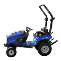
speed of 540 at approxi-
matel
y
2484 en
g
ine rpm.
Normall
y
, the PT
O
speed should be between 540 and
6
00.
O
peratin
g
the PT
O
at a speed above 600 is too
f
ast, and ma
y
result in a breakdown o
f
the tractor or
implement.
H
ourmeter in center of
g
au
g
e indicates en
g
ine and
tr
ac
t
o
r
use
t
o
ass
i
s
t in m
a
int
e
n
a
n
ce
int
e
rv
a
l
s
. Th
e
e
xtreme ri
g
ht di
g
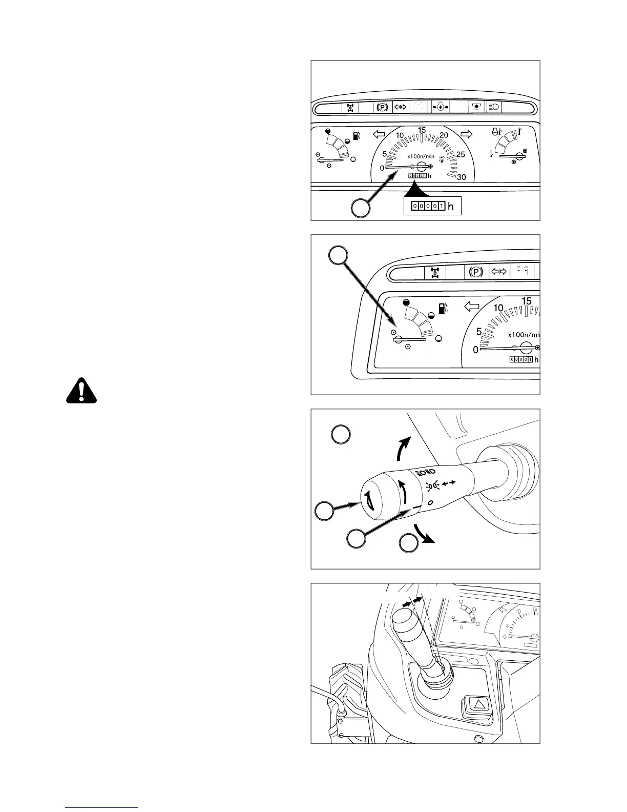
it indicates 1/10 hour increments.
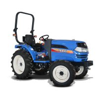
Fuel Gau
ge
FIG. 4-8
:
Gau
g
e, 5, indicates level of diesel fuel in fuel
tank when main switch is “
O
N
NOTE: Use onl
y
clean diesel fuel and clean area to
p
re vent dirt/water entr
y
into fuel tank when
r
e
f
illing. D
O
N
O
T run out o
f
f
uel as bleeding
a
ir from the s
y
stem will be required. Keep
f
ue
l t
a
nk f
u
ll t
o
minimiz
e
co
n
de
n
sa
ti
o
n.
CAUTION: DO NOT refill fuel tank with en-
g
ine runnin
g
or hot. Allow coolin
g
period.
D
O NOT smoke near fuel tank. Clean u
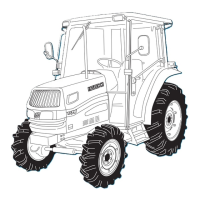
p
a
n
y
spilled fuel
.
Horn / Li
g
ht Turn Switch
FIGS. 4-9 & 4-10
:
Horn
/
Li
g
ht Turn
S
witch.
Horn Switch, 6 - H
o
rn will
sou
n
d
wh
e
n
ce
nt
e
r
s
wit
c
h
button is depressed.
L
i
g
ht Switch, 7 - Is a rotar
y
switch with three operat-
in
g
positions
:
OFF- Full
y
counterclockwise. All li
g
hts o
ff
.
1s
t
- Front clearance lamps and rear tail li
g
hts.
2
nd - Main beam headlamps and rear tail li
g
hts.
N
O
TE: Passing switc
h
Passing switch is turned on when switch
knob is pulled to upward over the high beam
p
osition.
NOTE: When high beam is selected
(
2nd position
)
,
l
ight in indicator light will come on.
T
urn Switch, 8 -
O
perate switch handle in direction
Tractor is bein
g
turned. The appropriate flashin
g
am-
ber warnin
g
li
g
ht
(
R
O
PS-mounted
)
will operate as turn
s
i
g
nal. Return switch to center position to cancel.
FIG. 4-7
FIG. 4-
8
FIG. 4-9
FIG. 4-10
4
5
7
6
8
Turn switch RH
1st
2nd
8
Turn switch LH
high beam
passing

Table of Contents

Related product manuals