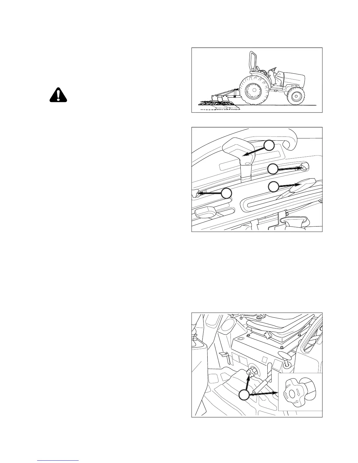
ine imple-
ments such as plows, subsoilers, cultivators, etc. are
.
NOTE: Refer to “Rear Linkage” for lockng pin details.
CAUTION: Do not use draft control when
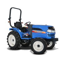
Lever Positions - Use position control lever,
1, to raise and lower implement and use draft control
in soil.
Position control lever, 1, can also be used to prevent
are encountered.
NOTE: Adjust lever stops, 3 and 4, can be set to con
act position control lever in implement work
r raised position. This enables implement to
e returned to identical setting after hitch ha
een raised for turning at field ends.
n Tractor and implement in
field and move position control lever, 1, forward
t control lever, 2, until correct
workin
depth is maintained.
When Turnin
- Move position control lever, 1, back-
ward to raise implement and permit completion o
turn. Return implement to work position b
osition control lever to previous position a
ort - Pull position control
soil texture or ground speed o
require slight readjustment of draf
control lever to maintain consistent working
epth as these can have a direct influence
t load.
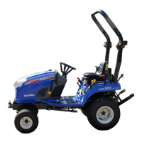
If erratic operation is encountered, turn lowerin
ate control knob, 5, clockwise to slow. Lowerin
location on Tractor will also decrease