EasyManua.ls Logo

Iseki TH4365 - Drawbar; Seat; Detaching Implements

Iseki TH4365
113 pages
Print Icon
To Next Page IconTo Next Page
To Previous Page IconTo Previous Page
Loading...
OPERATION
65
D
RAWBAR
FIG. 5-56
:
Drawbar, 1, at rear o
f
Tractor allows pull-
t
y
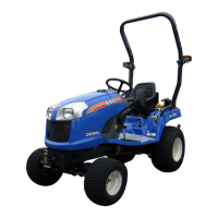
pe implements to be attached to Tractor. Maximum
vertical load on drawbar must not exceed
880
lbs
(
400k
g)
.
CAUTION: Pullin
g
heav
y
loads will require
e
xtended brakin
g
distances. Reduce
travel s
p
eed
.
M
ake sure attachment is properl
y
secured and sa
f
et
y
c
h
a
in i
s
used
.
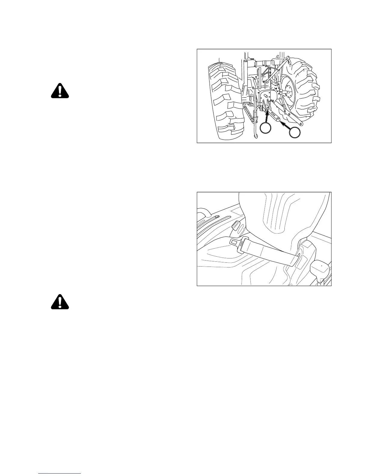
NOTE: When using three-point hitch, it ma
y
be
necessar
y
to remove drawbar b
y
removing
clips and pins, 2, and sliding drawbar from
b
racket to improve operating clearance. Thi
s
i
s particularl
y
true with mounted implement
s
using PTO drive.
Sea
t
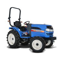
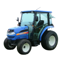
FIG. 5-57: Please ask the
y
our dealer if
y
ou have
an
y
question concernin
g
seat. Just
f
or
y
our in
f
orma-
tion, depend on
y
our resident area, seat belt will be
r
equired to equip as standard.
D
etachin
g
Implements
CAUTION: Alwa
y
s use POSITION CON-
T
ROL to attach/detach im
p
lements to
p
rovide
p
recise control of hitch
.
S
elect a level area to detach and store the implement.
Lower implement to
g
round b
y
movin
g
position control
l
ever to D
O
WN. If necessar
y
, ad
j
ust levelin
g
crank on
r
i
g
ht lift link to level implement on
g
round.
S
hut o
ff
en
g
ine, securel
y
lock brakes and remove ke
y
fr
o
m Tr
ac
t
o
r.
Disconnect implement PT
O
drive shaft
(
as applicable
)
.
Detach top link from implement and place in stora
g
e
p
osition on Tractor b
y
en
g
a
g
in
g
sprin
g
on top link in
s
lot in rear center panel.
NOTE: Lengthening or shortening of top link ma
y
b
e required to permit disconnection from
i
mplement.
FIG. 5-5
6
FIG. 5-57
1
2

Table of Contents

Related product manuals