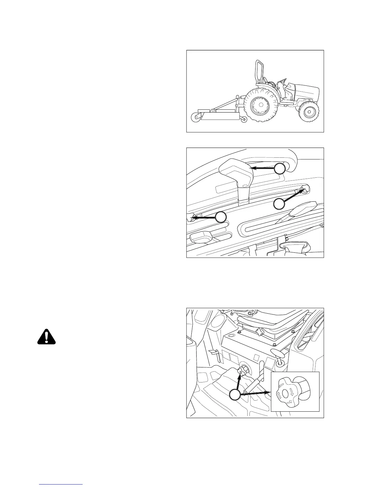
EasyManua.ls Logo

Iseki TH4365 - Using Position Control

Iseki TH4365
113 pages
Print Icon
To Next Page IconTo Next Page
To Previous Page IconTo Previous Page
Loading...
TH4295,4335,4365
60
U
sin
g
Position Control
FIG. 5-40
:
T
y
pe o
f
Work - Attachin
g/
detachin
g
imple-
ments and other operations requirin
g
implement to be
kept at constant hei
g
ht above
g
round. Also used with
tool bars havin
g
flexible row units and implements
e
quipped with
g
au
g
e
(
support
)
wheels.
FIG. 5-41
:
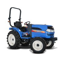
Lever Positions - Use position control lever,
1, to ad
j
ust hitch and implement position.
NOTE: Front lever stop, 2, can be set to contac
t
p
osition control lever in implement work posi
-
t
ion. This enables implement to be returne
d
t
o identical position after hitch has been
r
aised for turning, transporting, etc. Rear le
-
ver stop,
3
, can be set to limit raising height,
if
required.
To Be
g
in Work - Ali
g
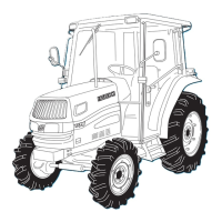
n Tractor and implement in field
and move position control lever, 1,
f
orward
(
toward
D
O
WN
)
. Ad
j
ust implement hei
g
ht usin
g
position
c
ontrol lever and set ad
j
ustable stops, 2 and 3, as
des
ir
ed
.
When Turnin
g
- Move position lever, 1, backward
(
to-
ward UP
)
to raise implement. Finish turnin
g
and return
l
ever a
g
ainst stop to resume operation.
To Finish Work and Transport - Move position control
l
ever, 1, full
y
rearward in quadrant.
FIG. 5-42
:
Lowerin
g
speed can be read
j
usted as nec-
e
ssar
y
usin
g
lowerin
g
rate control knob, 4.
CAUTION: When usin
g
mounted imple-
m
ents with PTO driveline, make sure
:
P
TO drive shaft has minimum 51 mm
(
2”en
g
a
g
ement of telescopin
g
sections,
a
t all hitch
/
im
p
lement
p
ositions
.
Hitch hei
g
ht durin
g
raisin
g
does not bind
drive shaft universal
j
oints due to extreme
drive shaft an
g
les. Limitin
g
raisin
g
hei
g
ht
m
a
y
be required
.
P
TO drive is disen
g
a
g
ed durin
g
transport
.
2
1
3
4
FIG. 5-40
FIG. 5-4
1
FIG. 5-42

Table of Contents

Related product manuals