FOR MECHANICAL & E6-
HST MODEL
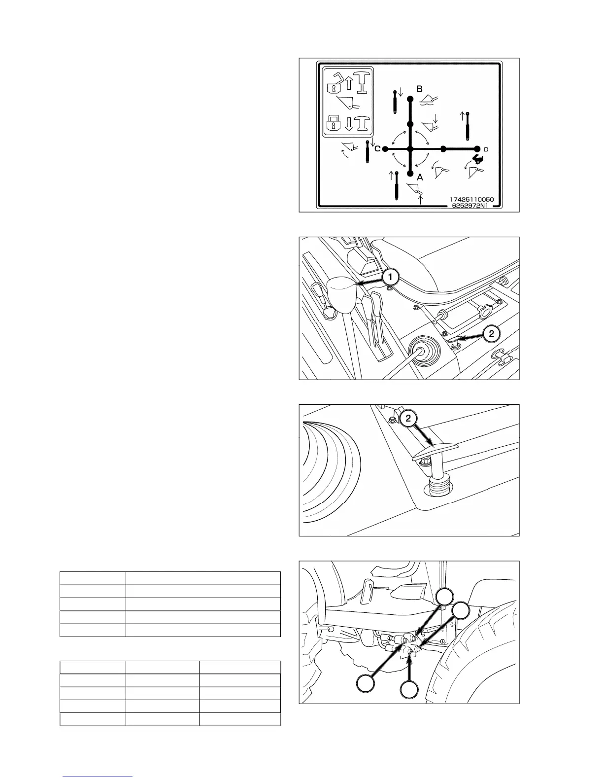
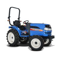
le-lever control, 1, provides
stick”
operation of auxiliar
lever backward and
forward moves the A/B spool in control valve respec-
tivel
orward will retain lever in
osition to allow attachment to follow
lever side-to-side moves the C/D valve spool
and controls Loader bucket position. Pullin
t will curl bucket and pushin
ht will dump
the bucket. Pushin
enerative” position, allowin
. When used with a blade an
can be controlled.
All positions
will return to neutral posi-
tion when lever is released. When in Float, the A/B
valve spool is held b
detents and the lever will have
to be pulled rearward to disen
e the detents.
NOTE: Inabilit
indicate the need for control
od adjustment at base of control lever.
Jo
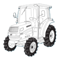
tick lockout 2 is a T-handle located near the
stick, put T-handle in the down
osition. When the T-handle is in the down position,
the
stick cannot be operated.
To unlock
stick, pull the T-handle up. When the T-
andle is in the up position, the
stick can be operated.
NOTE: If the T-handle is not pulled all the wa
he T-handle will return to the down position
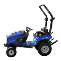
utput ports are located under the ri
ht step.
1. The output ports are identified b
letters, A,B,C,D,
from left to ri
ht as indicated on output ports.
2. The
chart provides correct output port
url
D Bucket Dump and Dump quickl
3. For other operations, except for loader work use the
followin