EasyManua.ls Logo

Iseki TH4365 - Joystick and Auxiliary Hydraulics

Iseki TH4365
113 pages
Print Icon
To Next Page IconTo Next Page
To Previous Page IconTo Previous Page
Loading...
INSTRUMENTS & CONTROLS
4
1
L
owerin
g
Rate Control Kno
b
FIG. 4-42
:
The lowerin
g
rate knob, 1, ad
j
usts the rate
o
f
drop o
f
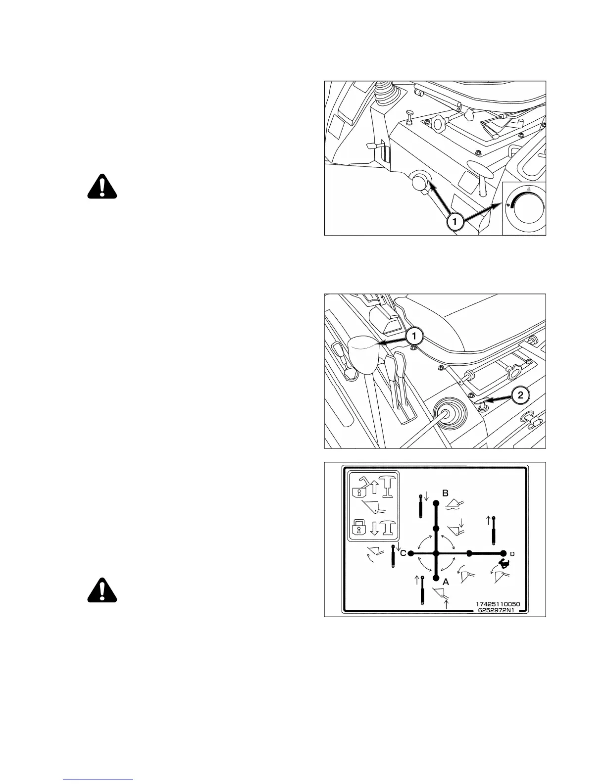
the three-point hitch and implement. Turn
k
nob clockwise to slow drop rate
(
increase lowerin
g
time
)
, counterclockwise to increase drop rate
(
de-
c
rease lowerin
g
time
)
. Turnin
g
the knob full
y
clockwise
will lock the implement
(
or hitch
)
in raised position for
transport.
CAUTION: When workin
g
on or around
m
ounted implements, alwa
y
s lower to
g
round prior to work. If implement must
b
e raised, alwa
y
s block implement and
l
ower links securel
y.
JOYSTICK
Control Lever
(
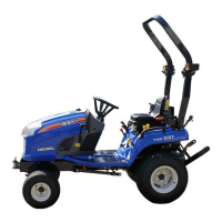
For Mechanical & E6-HST model
)
FIG. 4-43
:
The
j
o
y
stick control lever, 1, can be used to
determine the
f
ront loader boom position and bucket
p
osition. The lever is located to the front on the ri
g
ht
s
i
de
o
f th
e
sea
t.
FIG. 4-44
:
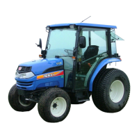
The Raise, Lower, Free Flow operations for
the boom, and Roll Back, Dump, Fast Dump opera-
tions
f
or the bucket can be controlled with the
j
o
y
stick
c
ontrol lever. The raise and lower operations for the
boom, and roll back and dump operations for the
bucket automaticall
y
return to neutral when the lever
i
s
r
e
l
eased
.
A detent device retains the
j
o
y
stick in the boom float
p
osition.
WARNING: Do not operate the
j
o
y
stick
e
xce
p
t when seated in the tractor. The
f
ront loader ma
y
operate unexpectedl
y
,
c
ausin
g
personal in
j
ur
y.
NOTE: When the jo
y
stick is operated on a tractor
w
ithout a
f
ront loader, the relie
f
valve ma
y
be
o
perated, causing the three-point link to stop
o
perating.
SEAT & SUSPENTION ADJUSTMEN
T
For ad
j
ustment o
f
the seat,
f
ollow the operator’s
m
a
n
ua
l
a
tt
ac
h
ed
with it.
FIG. 4-42
FIG. 4-4
3
FIG. 4-4
4

Table of Contents

Related product manuals