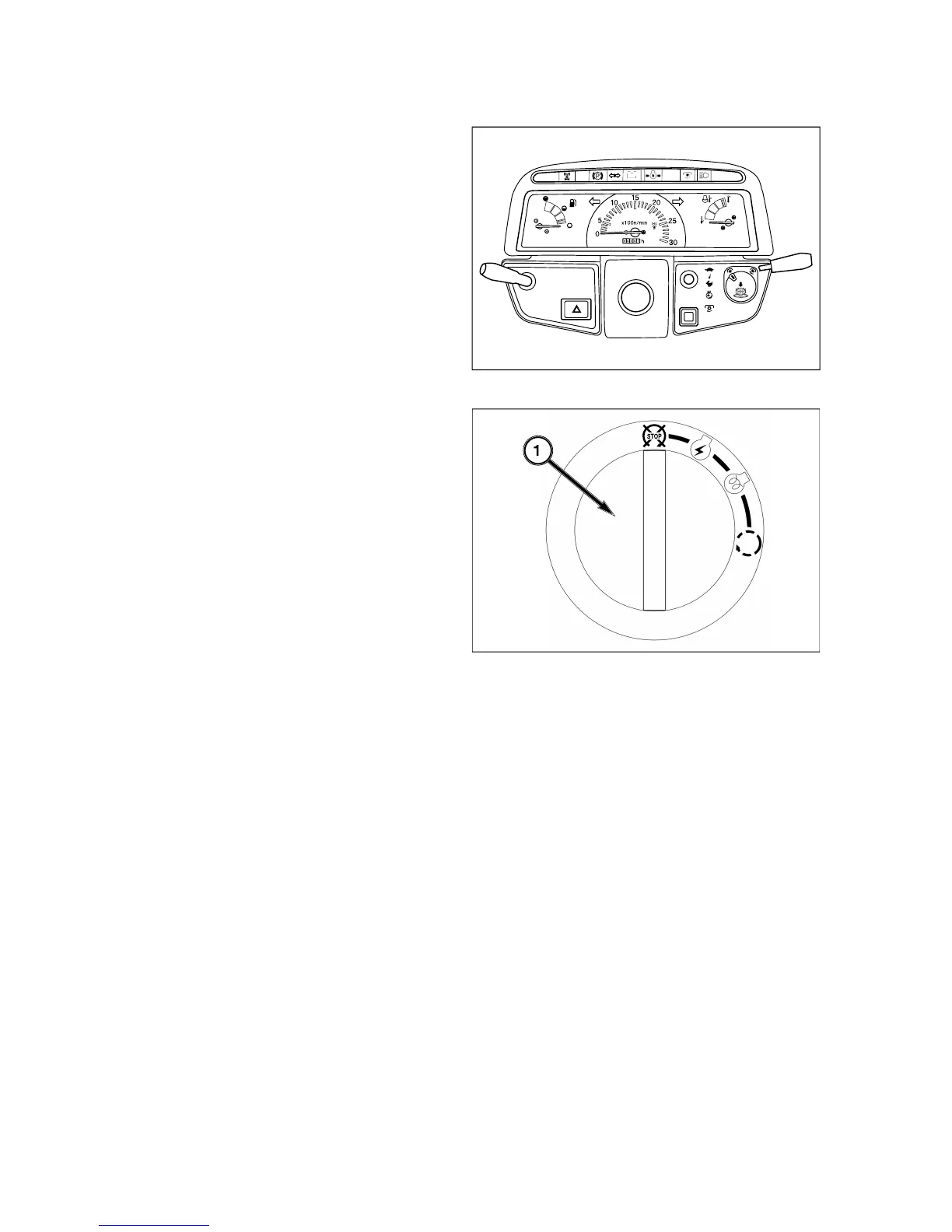
ontrol switches
and indicators located in instrument panel. Items are
detailed in the descriptions that follow
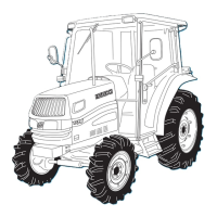
lectric Fuel Shut-Off
Turnin
main switch to off position will stop en
Main switch, 1, has the four followin
ine and all electrical circuits
off.
ht, turn/hazard posi-
tion li
- Power supplied to all circuits. Normal op-
ombustion chambers and assist startin
tarter activated. This position sprin
TE: Main switch must be turned to “
circuits will operate. PTO switch mus
e off and gear shift lever in neutral before
ngine can be started.
This tractor is equipped with an electric
hut off. When main switch
is turned to
“start”, “on”, or “glow” position and gear shif
ever is placed in neutral, a solenoid move
uel linkage on injection pump to run
osition to start engine. When main switch i
urned to “off”, solenoid moves fuel linkage to
ff position to stop engine.