Three-point hitch combines Tractor and implement
into one workin
unit. Implement position and raisin
. In addition, implement
wei
ht and loads impose downward pressure at Trac-
t
n.
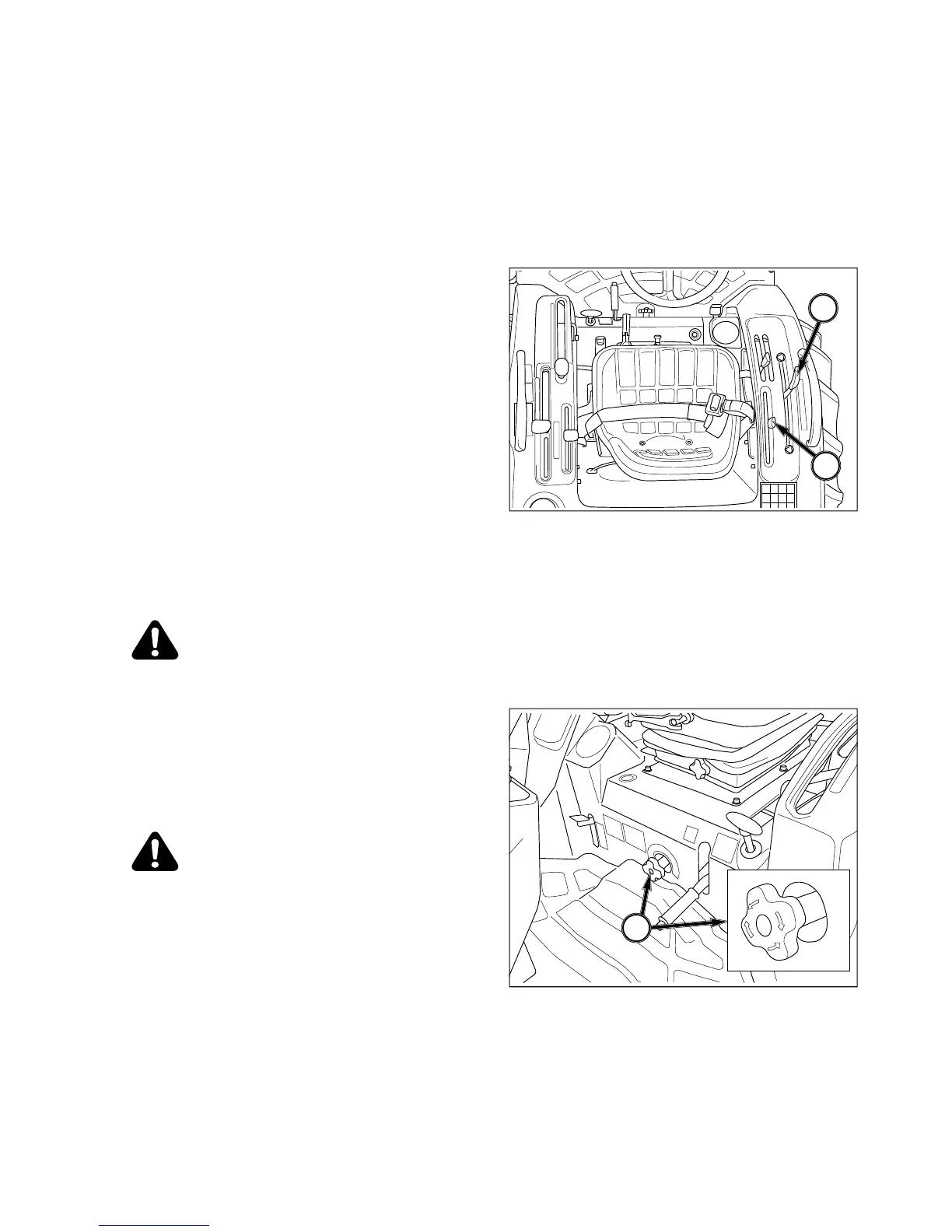
Hitch Controls
FIG. 5-31
stem to provide the followin
osition Control - Maintains hitch position at con-
ht in relation to the Tractor. As position con-
trol lever, 1, is moved rearward, hitch
lever forward will lower hitch to se-
ected position. Each lever settin
draft control lever, 2,
forward will provide deeper implements workin
lever backward will provide a shallower depth.
As
stem will raise or lower implements as needed
to keep even load in Tractor.
CAUTION: Use
osition control lever, 1,
when attachin
lace draft control lever, 2, full
Rate Control - Knob, 3, controls
dischar
hitch and implement. Turn knob clockwise to slow
drop rate, counterclockwise to increase drop rate.
Turnin
clockwise will lock implement in
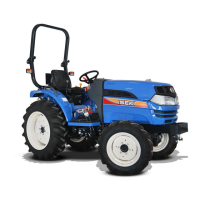
aised position.
CAUTION: When workin
round prior to work. If implement must