EasyManua.ls Logo

Iseki TH4365 - Page 67

Iseki TH4365
113 pages
Print Icon
To Next Page IconTo Next Page
To Previous Page IconTo Previous Page
Loading...
TH4295,4335,4365
6
4
CAUTION: Make sure all h
y
draulic hoses,
c
ouplers and c
y
linders are in
g
ood condi-
tion before use
.
FIG. 5-52
:
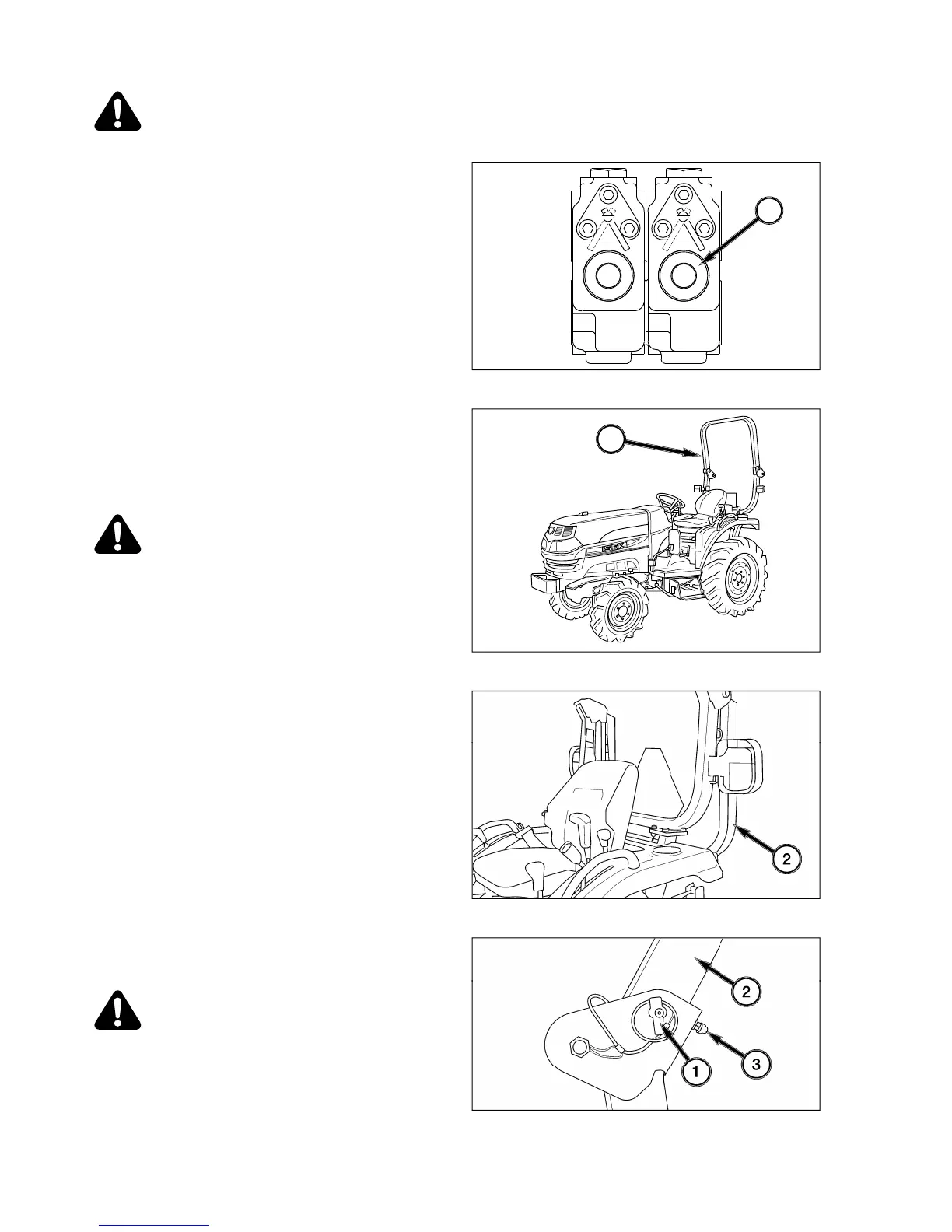
Most implements require double-actin
g
h
y
-
draulics. Each implement c
y
linder will have two hoses
co
nn
ec
t
ed
t
o
it.
When sin
g
le actin
g
service is required
(
c
y
linder with
onl
y
one hose
)
, the upper coupler will be used. The
s
elector function, 1, must be turned to the left. The se-
l
ector function is located at the ri
g
ht rear of the tractor
on the back o
f
the valve spools.
N
O
TE: For normal double-acting operation selector
function must be turned to the right.
RO
LL-
O
VER PR
O
TECTIVE STRUCTURE
(
R
O
PS
)
FIG. 5-53
:
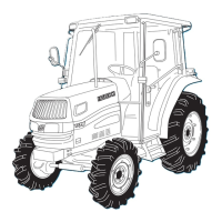
This tractor is equipped with a foldable roll-
over protective structure
(
R
O
P
S)
, 1, and seat belt.
Th
e
sea
t
be
lt
s
h
ou
l
d
be
w
o
rn
a
t
a
ll tim
es
wh
e
n tr
ac
t
o
r
is bein
g
operated with the R
O
PS in the upri
g
ht, locked
p
osition.
CAUTION: Do not weld, drill, bend or
strai
g
hten dama
g
ed ROPS. Make sure
a
ll components are in correct workin
g
order in order to
p
rovide the intended
p
rotection
.
Onl
y
ori
g
inal bolts and pins, or equivalent
r
eplacements, must be used and ti
g
ht-
e
ned to the correct tor
q
ue value. Make
sure the hin
g
e
j
oint is properl
y
secured
.
FIG. 5-54
:
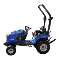
When overhead clearance is restricted, the
u
pper portion, 2, o
f
the R
O
P
S
ma
y
be
f
olded down.
FIG. 5-55
:
To
f
old the upper portion o
f
the R
O
P
S
, re-
move the lockin
g
pin, 1, and lower the upper portion.
The seat belt should not be worn when operatin
g
with
the R
O
P
S
f
olded down.
WARNING: No roll-over
p
rotection is
p
ro-
v
ided when the ROPS is folded down
.
D
rive with extreme care. Tractor roll over
m
a
y
result in serious in
j
ur
y
or death
.
Ad
j
ust the rubber isolator, 3, on the upper-front of the
l
ower U-
f
rame to reduce viblation. Ti
g
hten the
j
am nut.
1
1
FIG. 5-52
FIG. 5-5
3
FIG. 5-5
4
FIG. 5-55

Table of Contents

Related product manuals