EasyManua.ls Logo

Iseki TH4365 - Page 88

Iseki TH4365
113 pages
Print Icon
To Next Page IconTo Next Page
To Previous Page IconTo Previous Page
Loading...
LUBRICATION & PERIODIC MAINTENANCE
85
FIG. 6-30
:
G
eneral la
y
out and location o
f
electrical
sy
stem components and
f
uses
:
1 Main
f
use box - Located on ri
g
ht side o
f
the
s
teerin
g
post.
Ref Am
p
Function
1
3
APT
O
2
5
A
F
uel Pum
p
3
1
0
A Alt
e
rn
a
t
o
r
a
n
d
M
o
nit
o
r
41
5
A Work Li
g
ht
*
5
1
5
A
S
pare Power Suppl
y
6
5
AEn
g
ine Stop Rela
y
7
1
5
A
H
ead Li
g
h
t
8
1
5
A Turn/Warnin
g
Li
g
hts
*Work li
g
ht
(
rear
)
is an accessor
y
.
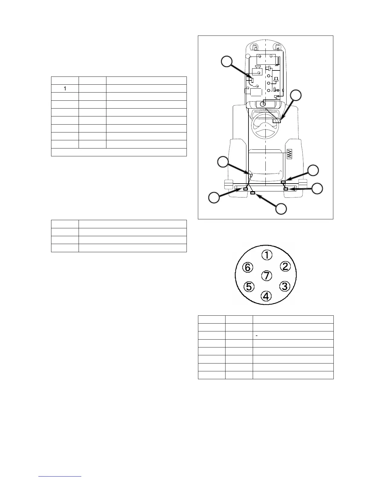
2 Slow blow fuses - In-line fuses protect relevant
c
ircuit b
y
meltin
g
when sustained heav
y
electrical
l
oad or short circuit is encountered, and
f
eature
a dela
y
ed action to prevent the current disruption
when brief sur
g
es are encountered. The slow-
blow fuses are located on the ri
g
ht-hand side o
f
the en
g
ine.
Am
p
Function
4
0
Alternator circuit
(g
reen
)
4
0
En
g
ine stop solenoid
(g
reen
)
4
0
M
ain circuit
(g
reen
)
NOTE: Failure of the main circuit fuse is usuall
y
caused from incorrect polarit
y
(
such a
s
r
eversed cables when using a booster bat
-
t
er
y)
. Failed
f
use will not allow batter
y
to be
charged during normal operation.
I
MPORTANT: Fuses are of specific amperage ca
-
p
acit
y
f
or the circuit in which the
y
are
l
ocated. Do not replace fuses with un
-
a
uthorized parts.
3 External power 12v/50W
4 Rear work lamp connector 12v/50w x 2 - This
c
onnection is
f
or optional rear work lamps.
5
7 Pins socket - Provides electrical connection
f
or
tr
a
il
e
r
soc
k
e
t.
6
S
eat switch connector
FIG. 6-30
Ref
.
D
I
N
Function
L
L
ef
t T
u
r
n
52
-
31
G
roun
d
R
R
i
g
ht Tur
n
58R
Tail Li
g
h
t
5
4
S
top Li
g
h
t
58L
Tail Li
g
h
t
2
1
6
3
4
5
4

Table of Contents

Related product manuals