System-Related Functions
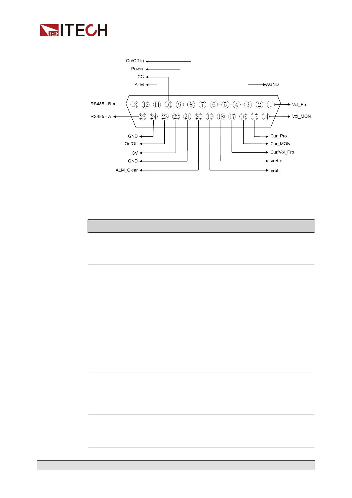
Figure 7–1 DB25 analog interface
Table 7–2 DB25 analog interface description
Pin Name Type Description
1 Vol_Pro Analog
input
Set the voltage, and input 0 ~ 10V volt-
age value to set the input voltage be-
tween 0 and full scale.
3–6 AGND Ground-
ing of
analog
signal
Grounding of all analog signals, includ-
ing pins: 1 (Vol_Pro), 14 (Vol_MON),
15 (Cur_Pro), 16 (Cur_MON), 17 (Cur/
Vol_Pro), 18 (Vref+) and 19 (Vref-).
2, 7, 12 Unused – –
8 On/Off_ In Digital
input
Control the On/Off state of the instru-
ment. When 0V is input, the instrument
state is switched to Off; when 5V is in-
put, the instrument state is switched to
On.
9 Power Digital
output
Indicate the instrument’s loading state:
Under normal loading state, 5V is out-
put; under non-loading state, 0V is
output.
10 CC Digital
output
Indicate the instrument’s working
state: Under the CC mode, 5V is out-
put; otherwise, 0V is output.
Copyright © Itech Electronic Co., Ltd.
74
 Loading...