System-Related Functions
10V and monitoring of voltage or current value between 0V and parallel full
range.
For example, the analog controls the current with range of 0 ~ 80A. When the
analog signal voltage is set to 5V, the instrument’s output or input voltage is set
to 40A; when the analog signal voltage is set to 8V, the instrument’s output or in-
put voltage is set to 64A.
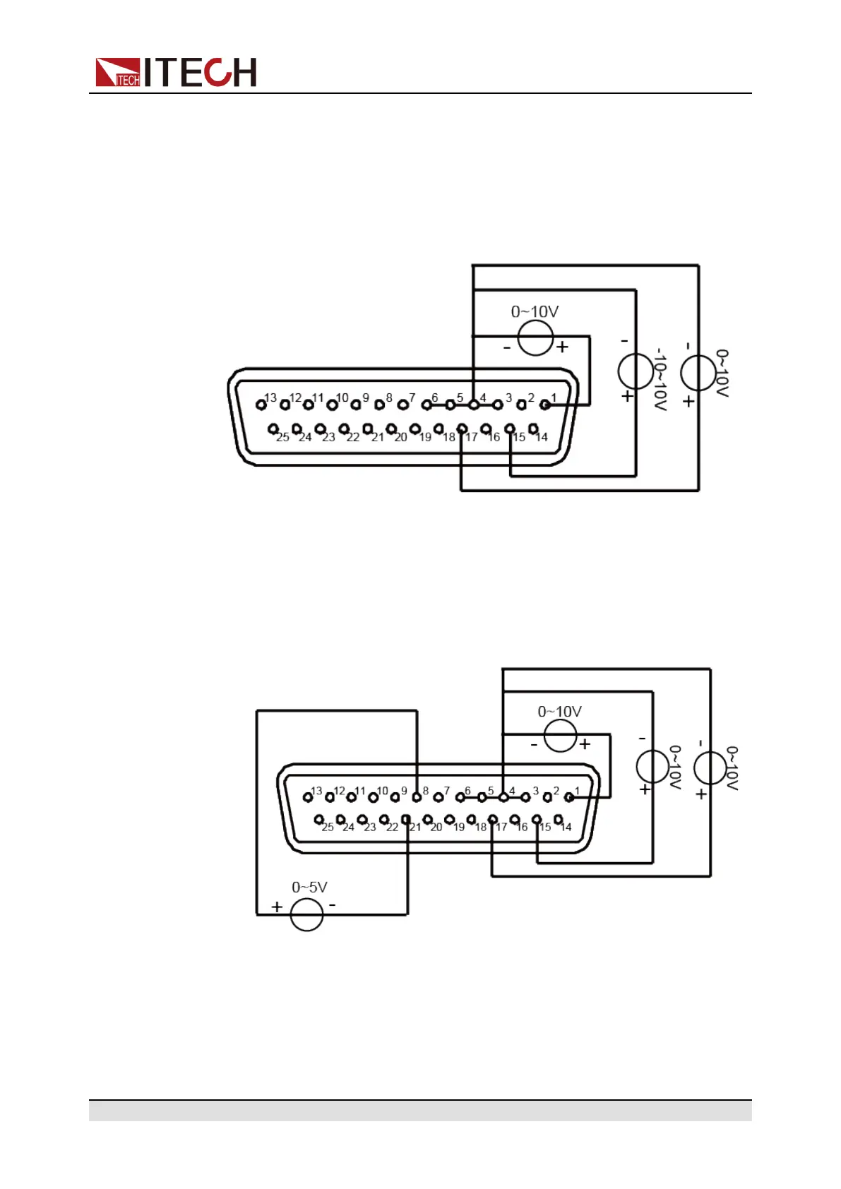
• Switch of On/Off state
The On/Off state can be switched remotely through the analog interface.
Connect an external DC power supply capable of outputting 0V and 5V be-
tween pin 8 (On/Off_In) and 21 (GND) of the analog interface. Other analog
input pins should also be connected correctly. The wiring method is shown
in the figure below.
When 0V is input, the instrument’s On/Off state is switched to Off state.
When 5V is input, the instrument’s On/Off state is switched to On state.
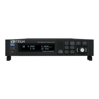
• Voltage and current monitoring
Through the analog interface, the existing output voltage/current or input
voltage/current can be monitored. Connect a digital voltmeter between pin
14 (Vol_MON), pin 16 (Cur_MOM) and ground wire 3/4/5/6 (AGND) of the
Copyright © Itech Electronic Co., Ltd.
77
 Loading...