System-Related Functions
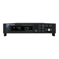
analog interface. Other analog input pins should also be connected cor-
rectly. The wiring method is shown in the figure below. The 0 ~ 10V voltage
reading corresponds to the power/load voltage and current output/input be-
tween zero and full scale. The wiring diagram is shown in the figure below.
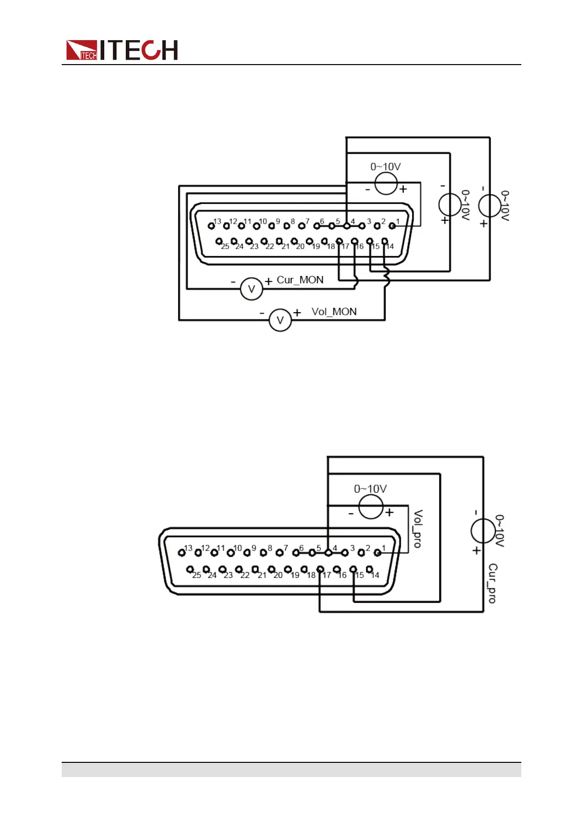
Voltage and current setting
The user needs to connect an external DC power supply capable of outputting
0V ~ 10V between the voltage setting pin 1 (Vol_Pro), current setting pin 17
(Cur/Vol_Pro) and ground wire 3/4/5/6 (AGND). Other analog input pins should
also be connected correctly. The wiring method is shown in the figure below.
Copyright © Itech Electronic Co., Ltd.
78