Appendix B pg. 2 ITW Dynatec c. 2003
Revised 2/05 DY2008 Controller Manual #50-14
Electrical Connector
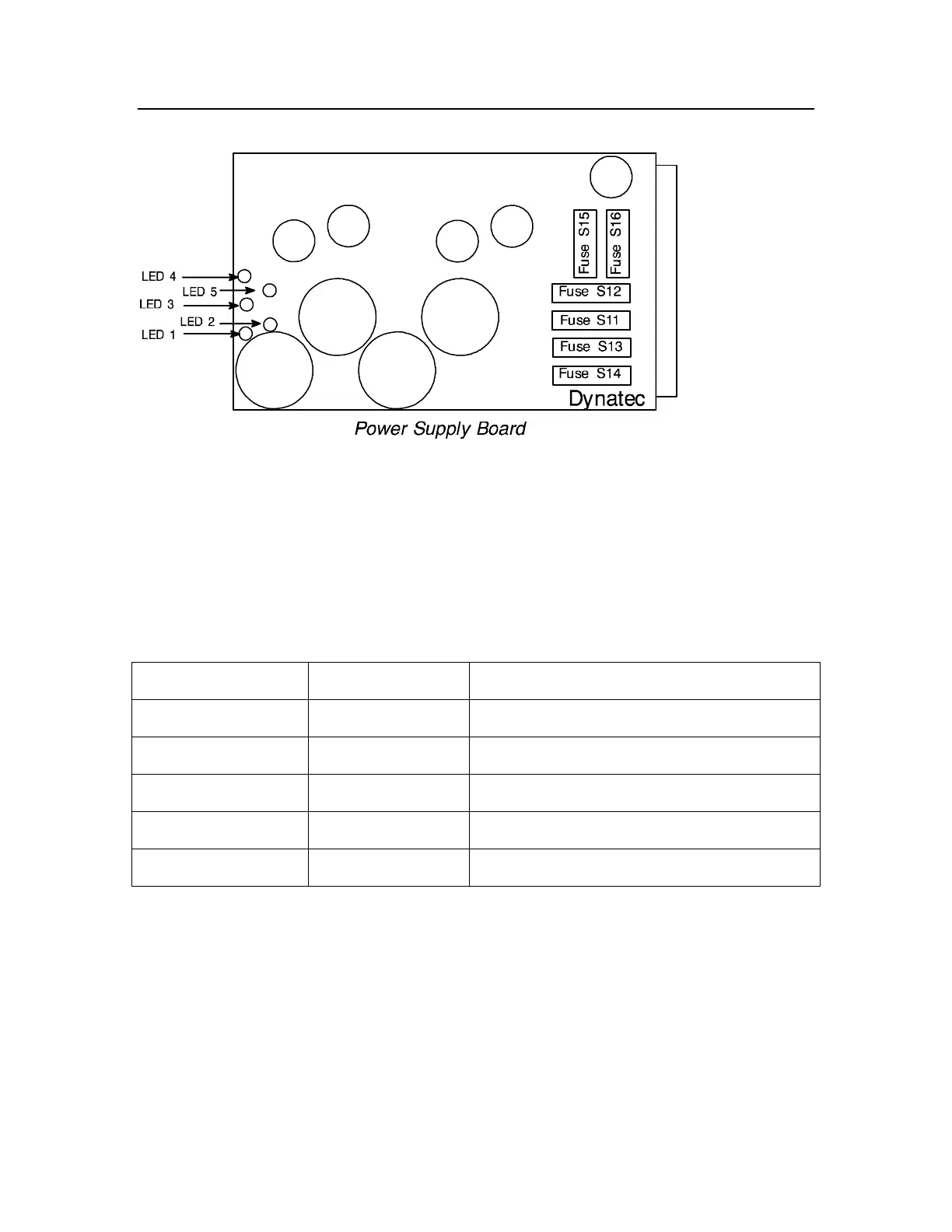
LED Indicators
There are five green light-emitting diodes (LEDs) on the exposed edge of the Power
Supply Board. All five of these LEDs should be brightly illuminated when the card is
properly assembled into the DY2008 Card Cage and the unit is powered ON. Dimly lit or
darkened LEDs indicate a fault somewhere in the control system. Immediately contact
ITW Dynatec Technical Support for assistance in diagnosing the specific problem.
LED Function Information
Designation Voltage Function
LED 1 24VDC Drive Output Voltage
LED 2 55VDC Drive Output Voltage
LED 3 170VDC Drive Output Voltage
LED 4 24VDC Encoder, Triggers, Pressure Control Voltage
LED 5 5VDC Microprocesssor Control Voltage
Fuses
The only fuses in the DY2008 Control Unit are located on the Power Supply Board.
There are a total of six fuses on this board, each covered by a plastic shield protector. The
shield may be removed by using a small screwdriver to gently loosen the spring clips at
the ends of each fuse holder. Continuity for these fuses can be tested from the back side
of the Power Supply Board without the need for removing the plastic shields. There are
four (4) 3.15 amp (PN 111306) and two (2) 4.0 amp (PN 111305) fuses located on the
board.
 Loading...