ITW Dynatec c. 2003 Appendix B pg. 3
DY2008 Controller Manual #50-14 Revised 2/05
Fuse Function Information
Designation Amperage Function
S11 4.0A 24VDC and 55VDC for Drive Output
S12 4.0A 24VDC and 55VDC for Drive Output
S13 3.15A 170VDC for Drive Output
S14 3.15A 170VDC for Drive Output
S15 3.15A 24 VDC for Encoders, Triggers and Pressure Control
S16 3.15A 5VDC for Microprocessor Control
Driver Card (28.00002.100)
The Driver Card supplies output, 24VDC, 55VDC or 170VDC, for up to four channels
within the Control Unit. There is one of these boards for each four output channels of the
unit.
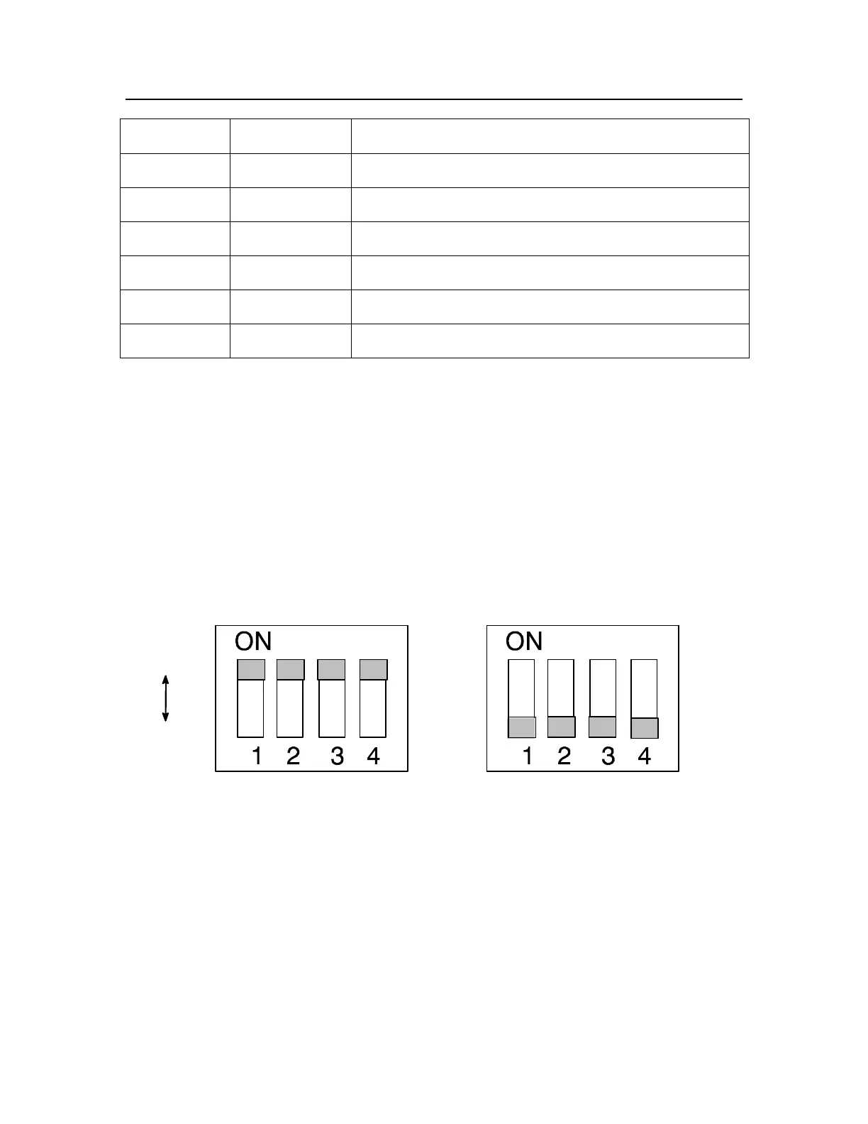
It is important when installing these cards, to assure the DIP Switch (A1), positions one
through four, are all turned ON for the Driver Card used for channel outputs 1 through 4
(Driver Card #1). All other Driver Cards should have all DIP switches set to the OFF
position. Failure to properly set the DIP switches could result in a malfunction of the unit
due to improper trigger input signaling.
Example: all sliding switches are ON Example: all sliding switches are OFF
ON position
OFF position
 Loading...