2-16
CHASSIS MODIFICATIONS
D
AILY 4x4
Base - May 2007 Print 603.93.761
Drilling the Chassis
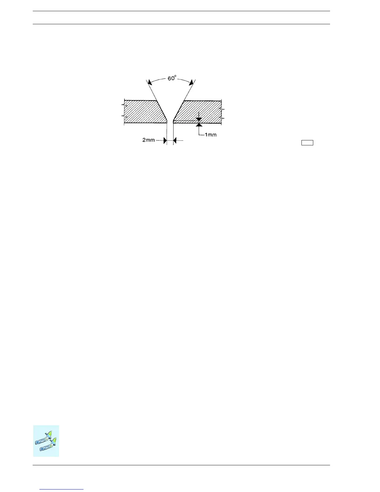
b) O n the i nner side of the side member give the parts that are to be joined a V-sh aped chamfer of 60° along the entire length
to be welded (see Figure 2.3).
91447
Figure 2.3
c) Arc weld in stretches using carefully dried basic electrodes. The recommended electrodes are:
For S 500 MC (FeE490: QSt E 500TM)
Diameter of the electrode is 2.5 mm, c urrent intensity approx. 90A (max. 40A for each millimetre of diameter of the electrode).
Using MIG-MAG welding use a welding rod with the same characteristics as the material to be welded (diameter 1 to 1.2 mm).
Recommended welding rod: DIN 8559 - SG3 M2 5243
gas DIN 32526-M21 or DIN EN 439
If FeE490 is used at very low temperatures, we recommend:
PrEN 440 G7 AWS A 5.28 - ER 80S - Ni 1
gas DIN EN439-M21
Avoid curren t overloading. Welding must be free from marginal cuts and waste material.
d) Repeat the operation on the reverse side by welding as detailed in point c).
e) Allow t h e side members to cool slowly and u n iformly. Cooling by air, water or oth er means is not permitted.
2.3.5 Closing of existing holes
If, when making new holes, the existing holes are found to be too close these may be closed up by welding. To ensure the success
of this operation the outer edge of the hole should be chamfered and copper plate used for the inner part.
For holes with a diameter of over 20 mm, chamfered plugs may be used, welded on both sides.

 Loading...
