CHASSIS MODIFICATIONS
2-27
DAILY 4x4
Print 603.93.761 Base - May 2007
Installing a Supplementary Axle
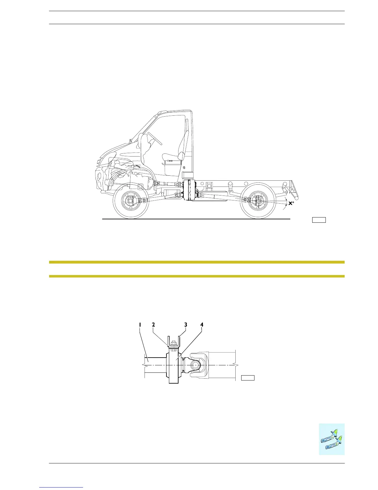
2.8.2 Determining Driveshaft Positions
In the case of a drive line consistin g of several sections, each shaft must be approximately the same len gth . As a general rule,
the difference in length between an intermediate and a sliding shaft (see Figure 2.9) must not exceed 600 mm; while between two
intermediate shafts the difference must be no greater than 400 mm. For sliding shafts there must be a margin of at least 20 mm
between the minimum working length and the fully c losed length.
Complying with the useful travel, position the static arrangement in an area as c entral as possible.
120362
Figure 2.9
X˚ <10˚
If the wheelbase is lengthened considerably, it may be necessary to apply an extra propeller shaft between the reduction unit/transfer
box and rear axle. In this c ase, the angle between the various propeller shafts must be constant and contained within the maximum
limit envisaged in production (see Figure 2.9).
It is absolutely forbidden to move the transfer box.NOTE
The elastic supports must be fitted with supporting plates at least 5 mm thick (see Figure 2.10) joined to cross members with
similar specifications to the IVECO specifications.
Fi

 Loading...
