2-26
CHASSIS MODIFICATIONS
D
AILY 4x4
Base - May 2007 Print 603.93.761
Installing a Supplementary Axle
The greater thickness of the tube depends on the cl ass, i.e. on the torque that the original shaft has to transmit and on th e design
of the driveline (torque, ratios of kinematic chain, power axle load).
A reference value for the thickness of the tube of a general validity cannot be given. When, for example, a tube of a larger diameter
is to be used, its thickness should theoretically be reduced until the torsional strength of the original tube is achieved. It should
however be noted that, to determine the thickness of the tube, the following points are to be taken into account: the size of the
male element of the universal joint, the possible necessity of adapters and the sizes of the tubes available.
Therefore the thickness of the tube should be agreed upon as each occasion arises with the workshops authorised by the
manufacturers of the transmission shaft depending on its dimensions (i.e. size of the u n iversal joint).
The minimum operating length (from flange to flange) must not fall below 600 mm for t he sliding sections and 300 mm for the
intermediate sect ion s.
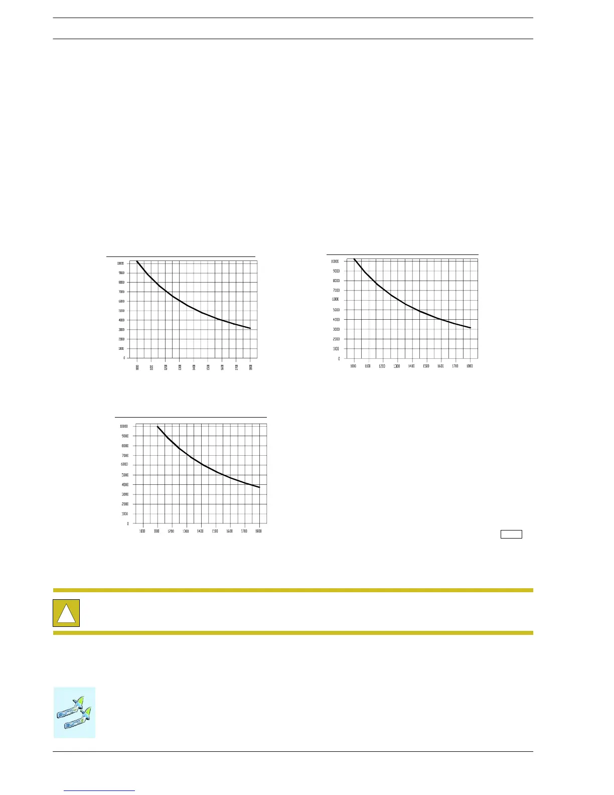
Table 2.14 - Obtainable propeller shaft characteristics
1410 CRITICAL TRANSMISSION SPEED - PIPE ∅ 76.2 x 2.4 mm
Maximum permitted rotating speed (rpm)
Distance between the LV joint centres (mm)
1310 CRITICAL TRANSMISSION SPEED - PIPE ∅ 88,9 x 1,65 mm
Maximum permitted rotating speed (rpm)
Distance between the LV joint centres (mm)
1310 CRITICAL TRANSMISSION SPEED - PIPE ∅ 76,2 x 2,11 mm
Maximum permitted rotating speed (rpm)
Distance between the LV joint centres (mm)
117798
!
The above obtainable maximum lengths refer to the original shafts. Shorter shafts (-10%) shall be
provided for the sections resulting from the conversion.

 Loading...
