THEORY OF OPERATION
THEORY OF OPERATION
General
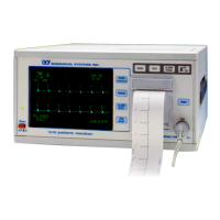
This section provides general descriptions of the circuitry in the R Wave Trigger patient monitor. Refer to the
schematic diagrams at the end of this manual to find the circuits described in this section. Also see the block
diagram in the Troubleshooting section for an overview of the signal flow in the monitor.
High Voltage Power Supply and Video Amplifier
Purpose of the High Voltage Power Supply
The High Voltage Power Supply generates every signal that goes to the crt except the yoke signals, which are
created by the Mother Board.
CRT Theory
Free electrons are created in the base of the crt by applying a voltage to the filament. A large voltage (6.5 kV in this
case) between the anode and cathode accelerate the free electrons from the filament to form a beam. This beam
strikes the phosphor at the face of the crt and forms a dot on the screen. The yokes, one horizontal (X yoke) and
one vertical (Y yoke), aim the beam by deflecting it with a magnetic field. This moves the dot across the screen, and
since phosphor takes some time to cool down, this forms a line across the screen when done quickly. The grids
(three in this case) can be biased to block the beam or to focus it. They are also used as intensity control.
Another way of changing the apparent intensity of the beam is to change the voltage at the cathode, or to quickly
switch the cathode on and off. Turning the crt beam on and off is often referred to as z axis control. This causes the
beam to appear and disappear. The phosphor holds some of the light from the beam while it is off, making it appear
that the beam is on but dim.
Raster and Stroke Written Displays
Two different strategies are used to display data on the crt: stroke writing for the waveform traces and vertical
raster writing for everything else. To simplify this explanation, we will break the screen down into three parts: a
vertical raster section on the left to show numbers and icons; as stroke written section in the center for writing
waveform data; and a vertical raster section on the right for writing scales, alarm messages, and menus.
The vertical raster written portion of the screen is divided into a grid of pixels, each pixel appearing at a fixed point.
The space between pixels, although small, is always off. As the beam is traveling vertically down one row of
pixels, the beam is turned rapidly on and off. It is on where a pixel is to be brightened and off where the pixel is
darkened. When the crt beam reaches the bottom of one row of pixels (one raster) a retrace occurs, sending the
beam to the top of the next raster to be drawn.
26 Model 101R/NR Service Manual

 Loading...