MONITOR DESCRIPTION
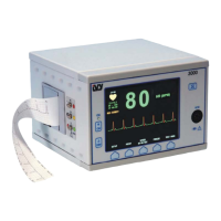
Display
HEART RATE: Displayed in beats per minute (bpm) on the upper left part of the screen.
SETUP: Selections made in the menu setup modes (alarm limits, lead selection, and filter on/off) are displayed in
small characters at the upper right corner.
ECG: Trace is displayed across the screen moving from right to left.
ALARMS: The following alarm indications are displayed in reverse video. Alarm indications appear on the upper
right portion of the screen and flash once per second except ALARMS OFF, which is displayed on the upper left
portion of the screen and is displayed as
.
: The audible alarms have been turned off.
LEAD OFF: A lead has become disconnected. This alarm cannot be reset with the
ALERT RESET key.
HR HIGH: The high heart rate limit has been exceeded for four seconds.
HR LOW: The low heart rate limit has been exceeded for four seconds.
ASYSTOLE: The interval between heartbeats has exceeded six seconds.
Rear Panel
The following are located on the rear panel.
POWER INPUT: A receptacle for a standard ac power cord.
When the monitor is connected to another piece of equipment through this rear panel connector, always make sure
that each piece of connected equipment has its own separate ground connection.
Do not attempt to connect cables to these connectors without contacting your Biomedical Engineering Department.
This is to ensure the connection complies with leakage current requirements of one of the following applicable
standards: UL 544, CSA 22.2 No. 125 or IEC 601-1. The maximum non-destructive voltage that may be applied to
these connectors is 5V.
TRIGGER OUTPUT: A BNC type connector for the output of the trigger pulse indicating the timing of the peak
of the R-wave. The output can be delayed from the peak of the R-wave through user controls.
QRS VOLUME CONTROL: A switch to control the QRS beep audio volume. Alarm audio is not affected.
PEQ GROUND: Potential Equalization - A ground connection that can be used to ensure that no potential
differences can develop between this equipment and other electrical equipment.
FUSE: Replace only with the same type and rating of fuse as indicated on the fuse rating label.
Model 101R/NR Service Manual
10
 Loading...