TESTING AND TROUBLESHOOTING
Adjustment Procedure
The following adjustments are not meant as field procedures. However, if these procedures are attempted, they
must be done correctly and according to the procedures listed here. See the Disassembly procedure in this manual
for removing the top cover.
Equipment Required
Digital Voltmeter Sine Wave Generator
Oscilloscope
ECG Simulator
ECG Signal
1. Press and hold the TEST button on the monitor's front panel.
2. With an oscilloscope, look at the signal at the X1000 output on the rear panel.
3. Adjust RV17 (ECG BAL) until the signal's baseline is at 0 V.
4. Adjust RV18 (ECG GAIN) until the peak signal is 1 V.
5. Repeat adjustments as necessary.
50/60 Hz Notch Filter
1. With the monitor's front panel controls, set the filter to ON and the lead selection to Lead I.
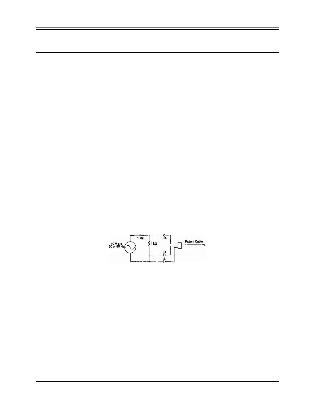
2. Insert a 10 mV p-p 50 or 60 Hz sinusoidal signal into the monitor's front panel ECG input. See the
diagram below for a suggested input circuit.
3. With an oscilloscope, look at the signal at the NOTCH test point on the Mother Board.
4. Adjust RV13 for 60 Hz and RV14 for 50 Hz for minimum amplitude signal at the NOTCH test point. This
signal should be ≤600 mV p-p. To turn on the correct filter set TP21 high (+5) for 60 Hz and ground for 50
Hz. A clip lead tied to +5 or ground will accomplish this.
5. From the front panel, set the filter to OFF. The signal at the NOTCH test point should be approximately 10
V p-p.
6. To test the auto notch function, plug unit into a variable freq. power generator and slowly change the line
freq. from 50 to 60 Hz.
Peak Detector
1. With the oscilloscope, look at the signal at U23 Pin 7.
Model 101R/NR Service Manual 43
 Loading...