TESTING AND TROUBLESHOOTING
High Voltage Power Supply
+275 V Measure at +275 TP Normal: +100 to +400 V
-100 V Measure at -100 TP Normal: -50 to -125 V
Key Signals
The following are a few signals to help verify the proper operation of the monitor. Use an oscilloscope and refer to
Mother Board layout for test point locations.
ECG Waveform
1. Press and hold the TEST button on the monitor's front panel.
2. Put the scope probe at the rear panel X1000 output. The signal should appear as 1 V peak pulses. The
same waveform should appear on the monitor's display. The rate indication on the display should be 70
bpm.
This verifies the operation of the ECG circuitry from very near the front of the monitor's ECG section. To
verify the remaining circuit, use a simulator at the ECG input to generate a 1 mV ECG signal.
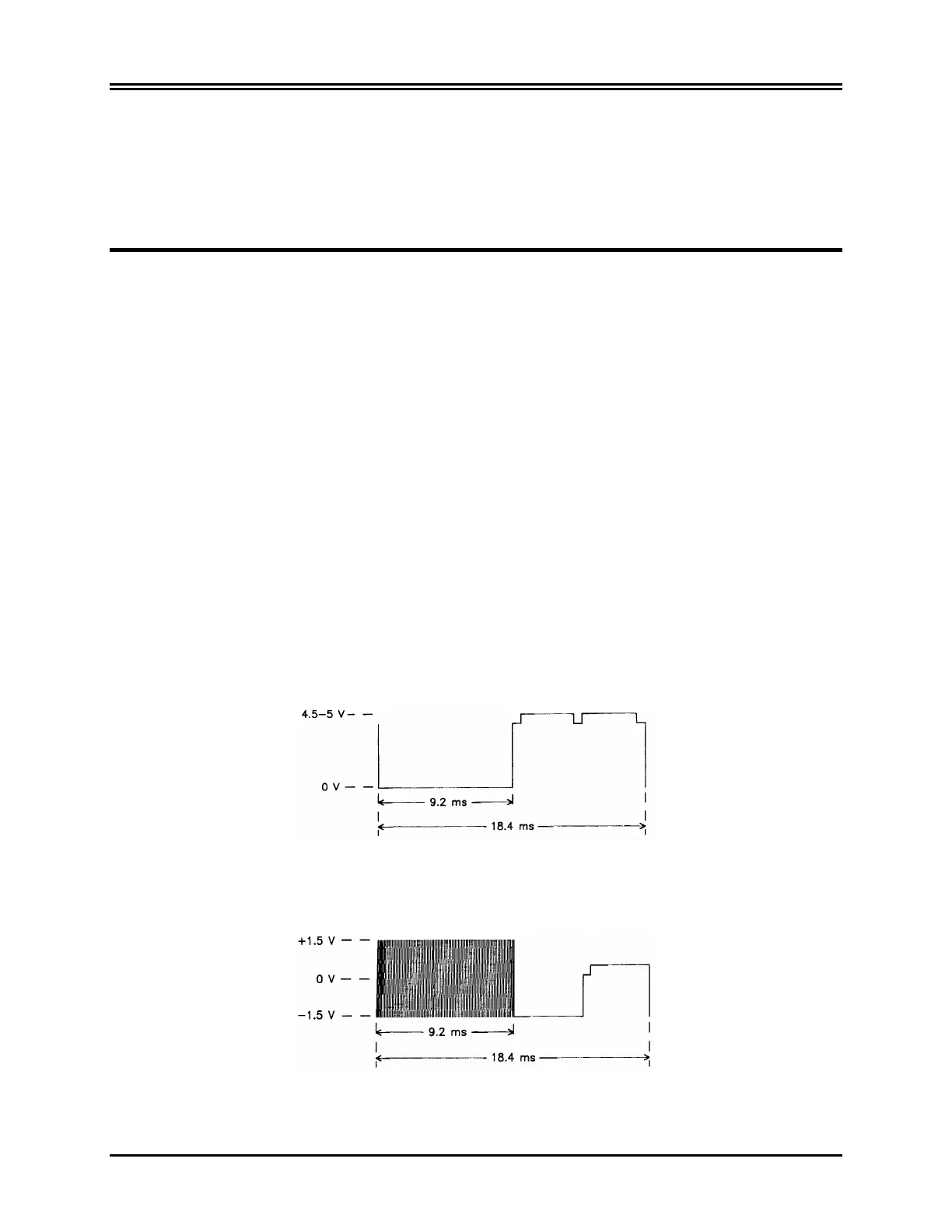
CRT Display
The following are signals generated by the Mother Board for creating the display. If these signals are correct but
the display isn't, the problem is not on the Mother Board. See Mother Board layout for test point locations.
For each of the following the signals, trigger the oscilloscope (negative) on Raster Enable (RE test point).
Raster Enable
RE Test Point
Vertical Deflection Signal
Vi Test Point
Model 101R/NR Service Manual 41
 Loading...