20
07610-004-33-05-E
INSTALLATION
INSTRUCTIONS
DRAIN LINE
CONNECTION
If water hardness tests at greater than 3 GPG, install the Scaltrol Water Treatment system
(see the Plumbing Options page) into the water line before the machine’s incoming water
connection point. If water hardness tests at lower than 3 GPG, install the water supply
line directly to the machine’s incoming water connection point. Iron in the water line
can cause staining. A lter designed to remove iron from the water supply is highly
recommended for supplies in excess of 0.1 ppm.
The manufacturer has an optional water pressure regulator (supplied on ER units only) to
accommodate areas where water pressure uctuates or is higher than the recommended
pressure (see the Plumbing Options page). The machine uses a ow pressure of 15
PSI for the incoming water line. Do not confuse static pressure with ow pressure. Static
pressure occurs when there is no ow and the valves are closed. Flow pressure occurs
when water is running into the machine. The pressure regulator should be adjusted to the
proper ow pressure indicated on the data plate.
The water supply line must be 1/2" NPT minimum and must be able to provide water at the
minimum temperature indicated on the machine data plate.
A shut-off valve (not supplied) should be installed to isolate the machine from the water
system in the event service is required. An optional shock absorber (not supplied) should
also be installed on the incoming water line (see the Plumbing Options page). This
prevents water hammer (hydraulic shock) from causing damage to the equipment.
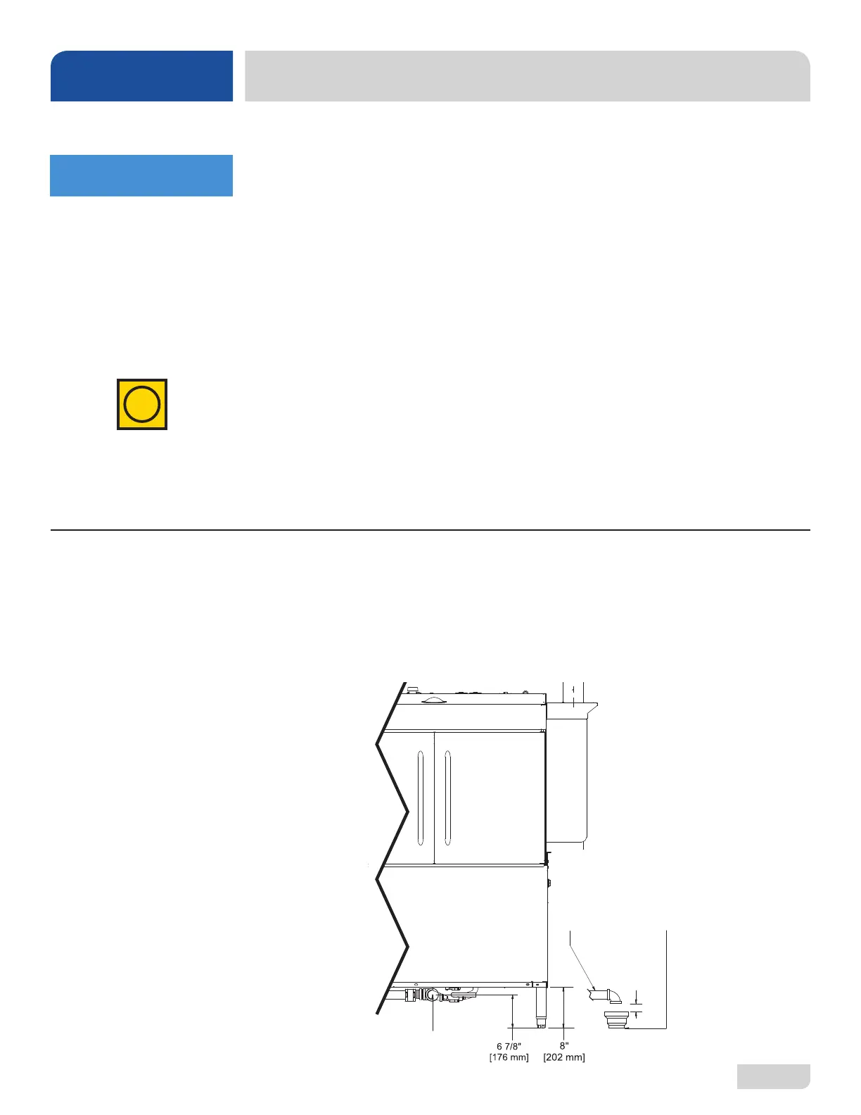
The drain for the machine is a gravity-discharge drain. All piping to the machine drain must
be a minimum 1 1/2” NPT and must not be reduced. There must be a minimum 1 1/2" air-
gap between the machine drain line and the oor drain or sink. The oor drain or sink must
be a minimum 3" NPT. If a grease trap is required by code, it should have a ow capacity
of 5 GPM. 44" units have one drain connection point and 66" units have two (connected
and drained into one facility oor drain or sink).
PLUMBING
i
Machine
Drain Line
1 1/2” [38 mm]
Minimum
Must NOT Be
Reduced
Must Install
Machine Drain
Line above
3” [76 mm]
Minimum Floor
Drain or Sink
1 1/2”
[38 mm]
Minimum
Air-gap
Drain
Connection
1 1/2” [38 mm]
A water hardness test
MUST be performed.