SPECIFICATIONS AND GENERAL INFORMATION
4181384 First Edition 2-3
2
If the machine requiring service is equipped with an
accessory kit, see Section 9, “Accessories and
Miscellaneous Repair” for removal, repair, and
installation procedures.
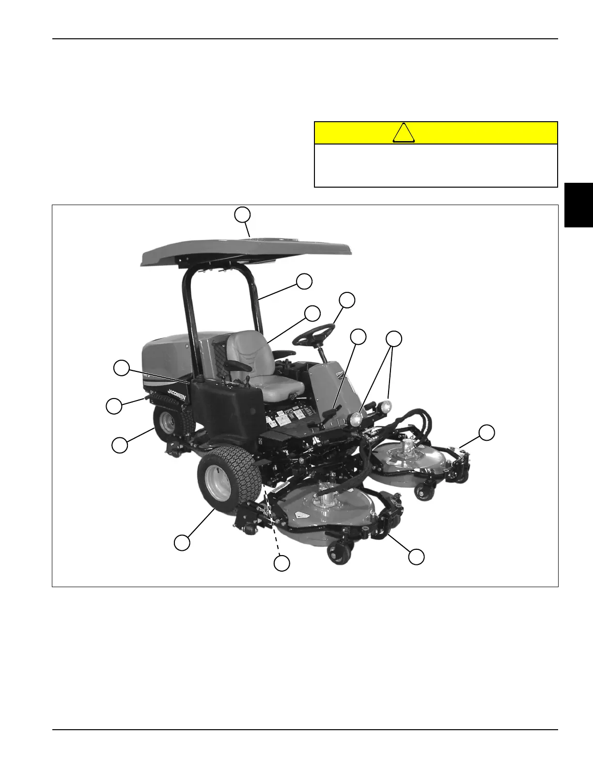
Component Location
AR-3
See Figures 2-3 and 2-4.
!
CAUTION
Figure 2-3: Component Location—Right Side
Become familiar with operator controls, machine
components, and correct operating procedures
before beginning repair procedures.
1 Canopy (Optional) 8 Right Front Cutting Unit
2 OPS (Optional) 9 Right Front Wheel Motor
3 Seat 10 Front Wheel (2)
4 Steering Wheel and Tower 11 Rear Wheel
5 Traction Pedal 12 Muffler
6 Work Lights (Optional) 13 Hydraulic Oil Tank
7 Left Front Cutting Unit
2
13
7
TN0991
1
8
11
6
3
5
10
4
12
9