4 CONTROLS
en-35
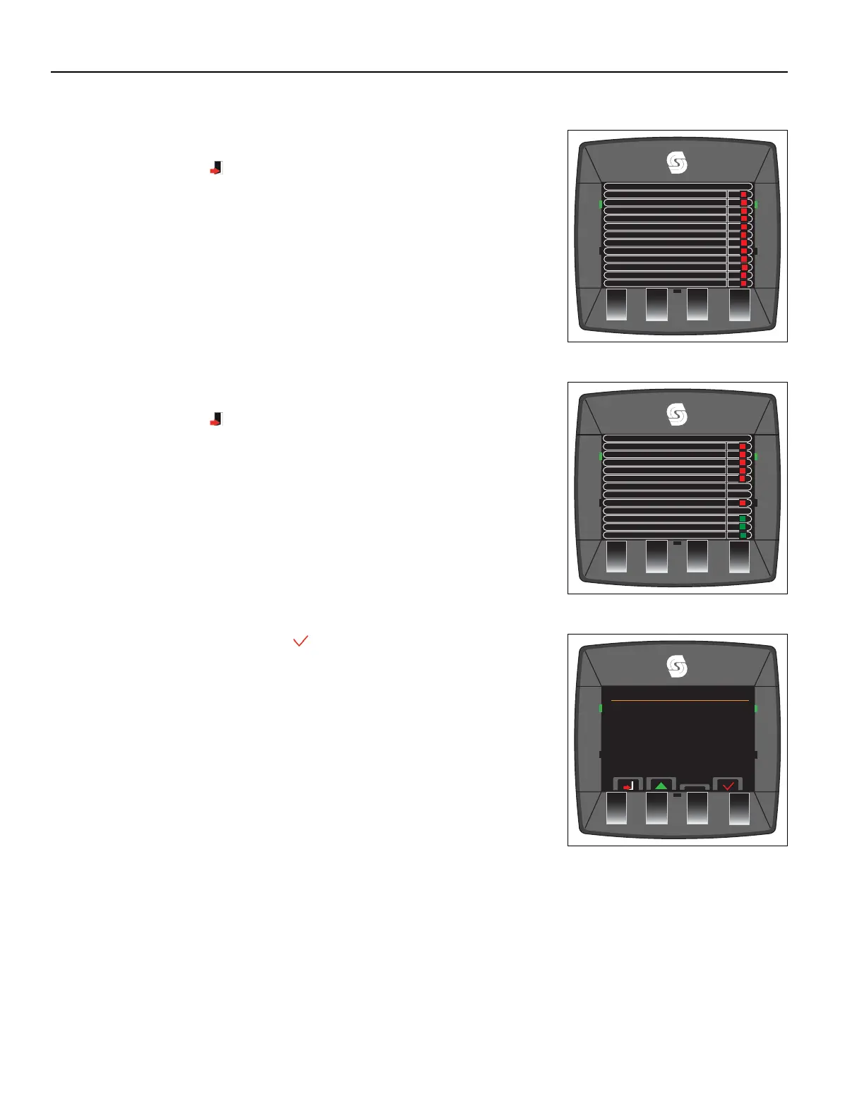
4.2.23.26 CONNECTOR J5 _______________________________________________________
This screen shows the status of the J5 connectors.
Press the left side button to return to I/O diagnostics menu.
On and OFF shown for illustration purposes only.
4.2.23.27 CONNECTOR J6 _______________________________________________________
This screen shows the status of the J6 connectors.
Press the left side button to return to I/O diagnostics menu.
On and OFF shown for illustration purposes only.
4.2.23.28 ECU (ENGINE CONTROL UNIT) MONITOR (J1939) ___________________________
Select the ECU Monitor and accept
Connector J5
J5-1 Center Deck LED Output
J5-2 Left Mow Solenoid
J5-3 Deck Lock Solenoid (3,4)
J5-4 Center Mow Solenoid
J5-5 Raise Enable Solenoid
J5-6Deck Lock Solenoid(1,2)
J5-7 Reverse Signal Output
J5-8 Right Mow Solenoid
J5-9 Inhibit Regen
J5-10 Deck Lock Switch Input
J5-11 Pressure Switch Input
J5-12 Service (EMG) Brake Switch
OFF
OFF
OFF
OFF
OFF
OFF
OFF
OFF
OFF
OFF
OFF
OFF
Connector J6
J6-1 Start w/Int Output
J6-2 Left Float Solenoid
J6-3 Right Float Solenoid
J6-4 Weight Transfer Output
J6-5 Backlap Solenoid Output
J6-6 Fused B+
J6-7 Fused B+
J6-8 Force Regen Switch
J6-9 GND
J6-10 Charge Filter
J6-11 Not Used
J6-12 Engine Neutral
O
O
O
O
O
ON
ON
ON
O
Service Menu
Fault Log
Time Until Service
Diagnostics
I/O Diagnostics
J1939 Info

 Loading...