ADJUSTMENTS 6
en-64
6.3 WEIGHT TRANSFER ADJUSTMENT __________________________________________
The weight transfer bias can be adjusted on the lift valve. The valve is accessible by removing the access panel in the
operator platform. The valve is situated on the right hand side.
To adjust:
1. Loosen the locknut A while holding the threaded shaft still with the Allen Key B.
2. Using an Allen key B rotate the threaded shaft clockwise in direction D to increase
weight onto the drive wheels when the traction control button is operated on the control
pod. This improves slope climbing performance. To reduce weight on the drive wheels
when the traction control button is operated on the control pod, rotate the threaded shaft
counter clockwise in direction C. This increases the ground weight of the cutting unit
and will reduce the possibility of cutting unit “bounce” when working at high speed on
undulating ground. It is recommended that the Allen key is turned a 1/4 turn at a time
and the weight transfer tested.
3. Tighten locknut A. while holding the threaded shaft still with the Allen Key B.
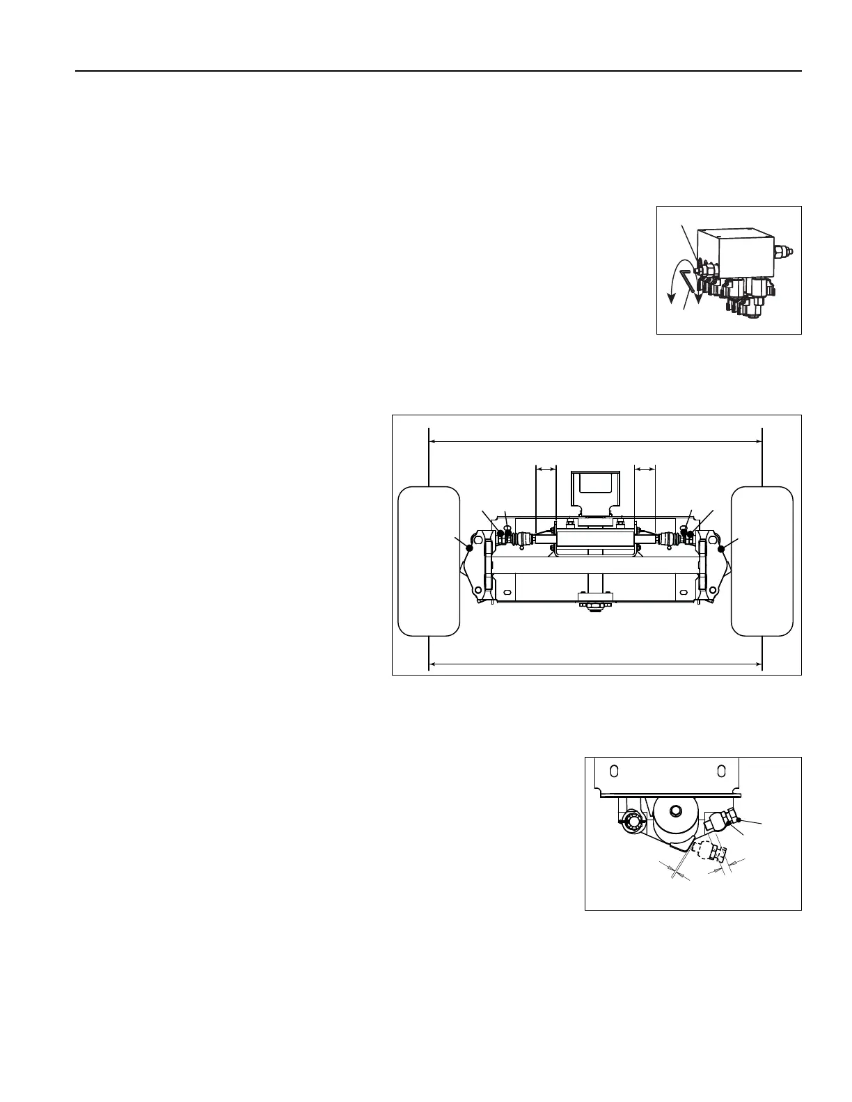
6.4 STEERING SHAFT ADJUSTMENT ____________________________________________
The rear motor mounts (A and B) must be
adjusted for 1/8 inch (3.2 mm) toe-in.
The steering ram shaft must be equal (C and D)
on both sides of the steering ram.
1. Apply Loctite 243 to nut (E) and steering link
(F).
2. Assemble rod end to steering link on both
side of axle.
3. Adjust rod ends for 1/8 inch (3.2 mm) toe-in.
The rod ends must be threaded equally onto
steering links and ram shaft must be equal
on both sides.
4. Torque the nuts (E) to 100Nm (74 lb-ft).
6.5 AXLE STOP ADJUSTMENT__________________________________________________
The rear wheels axle stops are set as follows.
1. Loosen the nut (A) and adjust bolt (B) to give a dimension of 15.9 mm.
2. Tighten nut (A) to 210Nm (155 lb-ft)
3. Repeat for opposite side of axle.
4. Check that left and right full steering lock is obtainable. When the steering is
at full lock during left and right turns, there must be 1 mm clearance
between the stop bolt and the welded axle stop.
C
D
A
B
A
B
D
G – 1/8 inch (3.2 mm)
G
C
E
F
E
F
15.9 mm
1 mm
A
B