Page 18
ENGLISH
Jandy
®
Legacy™ Model LRZE Pool/Spa Heater by Zodiac
®
|
Installation and Operation Manual
11. For an existing installation, remove the tube
gaskets and clean the header's mating surface of
any corrosion or debris. Replace the tube gaskets
with new ones. Do not use any metal tools on the
header surface. Scratches may compromise the
seal integrity.
12. Place the inlet/outlet header over the bolts
and gasketed tubes on the left side of the tube
assembly. Align the bolt and tube holes in the
header with the bolts and tubes in the header bar
and slide the assembly together. Refer to Figure 9.
Donotreversethepositionofthebypass.
13. Thread on the 10 bolts and washers and hand
tighten.
14. Place the return header over the bolts and
gasketed tubes on the right side of the tube
assembly. Align the bolt and tube holes in the
header with the bolts and tubes in the header bar
and slide the assembly together.
15. Thread on the 10 bolts and washers and hand
tighten.
Proceed as follows:
1. For an existing installation, drain the heater by
removing the two drain plugs on the inlet/outlet
header and the drain plug on the return header.
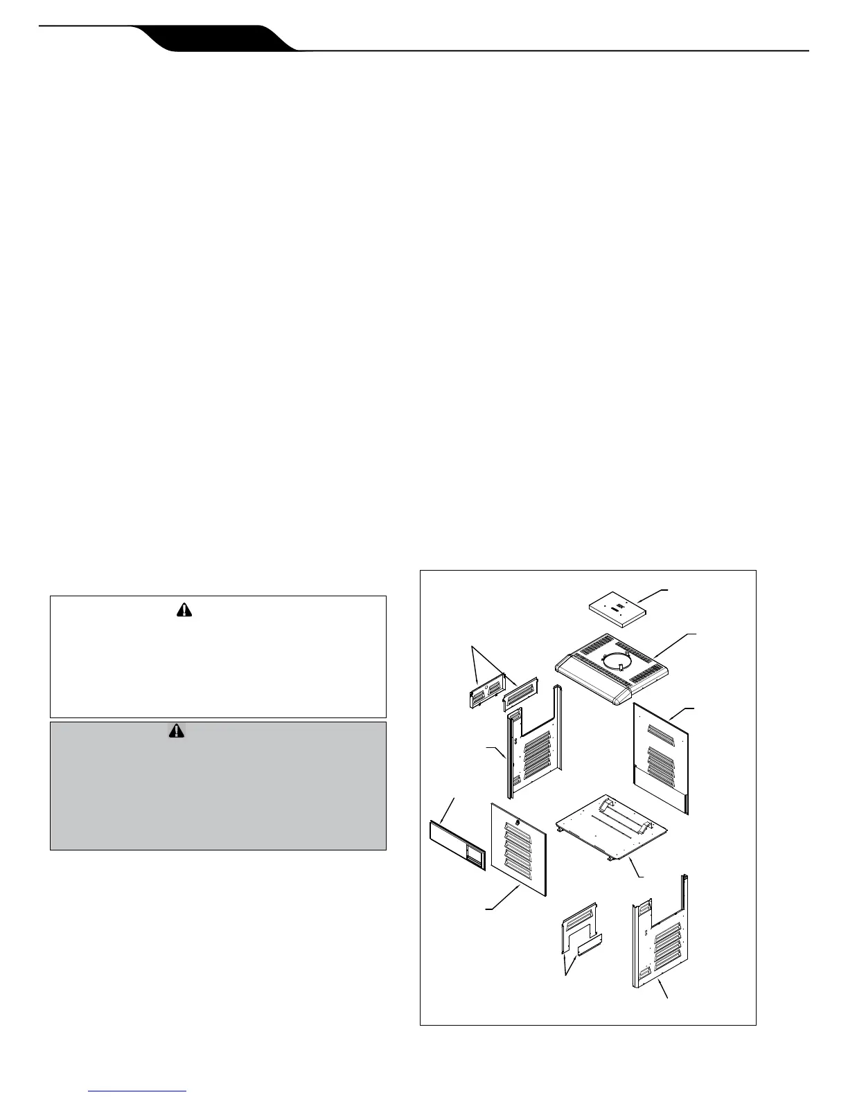
2. Remove the heater front panel (door).
3. Remove the I/O header side cover plates, top and
bottom. See Figure 10.
4. Remove the return header side cover plates, top
and bottom. See Figure 10.
5. Disconnect the blue "HiLimit" two-pin connector
from the Power Interface board on the raceway.
Clip any wire ties attached to the harness. Feed
the "HiLimit" two-pin connector and wiring back
through the way it is routed to the header so that
the harness hangs free from the header, outside of
the cabinet.
6. Disconnect the two "WATER TEMP" tempera-
ture sensor leads from the Power Interface board
on the raceway. Clip any wire ties attached to the
harness. Pull the wires out of the cabinet so that
they hang free from the header, outside of the
cabinet.
7. Disconnect the yellow "Water Press" two-pin
connector from the Power Interface board on
the raceway. Clip any wire ties attached to
the harness. Feed the "Water Press" two-pin
connector and wiring back through the way it
is routed to the water pressure switch so that
the harness hangs free from the water pressure
switch, outside of the cabinet.
Inordertopreventpropertydamageorinjury,
ensurethatthewiringishandledandrouted
carefullysoasnottocauseanydamagetoit.Ad-
ditionally,becarefulnottocreateanykinksinthe
waterpressureswitchcoppertubingwhenhandling
theheader.
And'empêcherdesdégâtsmatérielsoudes
blessures,assurez-vousquelecâblageest
manipuléetinstallésoigneusementdemanièreà
nepasl’endommager.Deplus,vousdevezfaire
attentionànecréeraucuneimperfectiondansla
conduiteencuivredel’interrupteurdepression
d'eauenmanipulantlatête.
8. For an existing installation, remove the coupling
nuts from the header and disconnect the water
supply from the heater.
9. Remove the 10 bolts and washers from the inlet/
outlet header and remove the header from the
tube assembly.
10. Remove the 10 bolts and washers from the return
header and remove the header from the tube
assembly.
RIGHT SIDE PANEL
IN/OUT HEADER
SIDE COVER PLATES
TOP AND BOTTOM
FRONT PANEL
(DOOR)
LEFT SIDE PANEL
CONTROL PANEL
RETURN HEADER SIDE
COVER PLATES
TOP AND BOTTOM
VENT TOP
TOP PANEL
REAR PANEL
BASE