Page 19
ENGLISH
Installation and Operation Manual
|
Jandy
®
Legacy™ Model LRZE Pool/Spa Heater by Zodiac
®
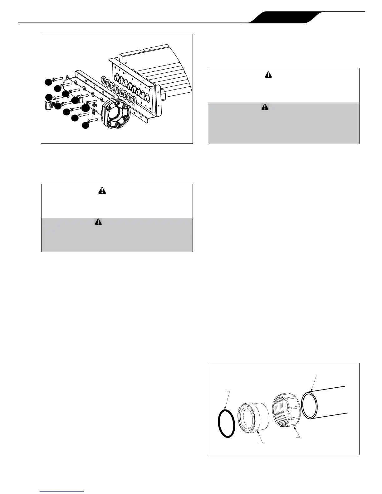
16. Use a torque wrench to tighten the bolts on each
header to 4 ft-lbs. The bolts must be tightened in
the sequence indicated in Figure 11.
Siletuyaucollecteurn’estpasserréconformément
auxdirectivesdesl'étape16,ilrisqued’avoirdes
fuitesoudes’endommagerdefaçonpermanente.
Failuretotightentheheaderasindicatedinstep16
maycausetheheadertoleakorbecomeperma-
nentlydamagedfromwarping.
17. Remove the 3/4 inch button plug located in the
left side panel below the inlet/outlet header and
replace with the 3/4 inch wire grommet from
the right side panel below the return header.
The high limit leads were routed through this
grommet prior to removal in step 5. Install the
3/4 inch plug in the opening where the 3/4 inch
wire grommet was removed.
18. Route the blue two-pin connector attached
to the high limit switches back to the Power
Interface board in the raceway. Reconnect the
blue "HiLimit" two-pin connector to the blue
"HiLimit" connector on the Power Interface
board.
19. Route the wires that attach to the temperature
sensor back to the Power Interface board in the
raceway. Reconnect the wires to the "WATER
TEMP" terminals on the Power Interface board.
20. Install the longer syphon loop tube (part number
R0483601) to the pressure switch and locate
the the pressure switch in the front area of the
cabinet.
21. Route the yellow two-pin connector that connects
to the water pressure switch back to the Power
Interface board in the raceway. Reconnect the
yellow two-pin connector to the yellow "Water
Press" connector on the Power Interface board.
22. Use plastic wire ties to refasten the temperature
sensor, high limit switch and water pressure
switch wires to each other. Bundle the wires near
the control panel and fasten them with a wire tie.
And'empêcherdesdégâtsmatérielsoudes
blessures,assurez-vousqu'aucundeslsn'est
encontactavecunbordtranchantouunesurface
chaude.
Inordertopreventpropertydamageorinjury,be
surethatnoneofthewiresareincontactwitha
sharpedgeorahotsurface.
23. Install the return header side cover plate on the
right side of the unit.
24. Install the I/O header side cover plates, top and
bottom on the left side of the unit.
25. Replace the front panel (door).
The Legacy Model LRZ electronic heater has
a standard two (2) inch water header and coupling
design. With this feature, only nominal two inch PVC
or CPVC may be connected to the heater. However,
by installing the appropriate pipe adapters and two
short pieces of two inch plastic pipe (supplied by the
installer), any size existing pipe may be tted to the
heater.
To connect a section of 2” PVC or CPVC pipe
to the heater, rst slip a coupling nut onto the pipe.
Then prepare the end of the pipe with the proper PVC/
CPVC primer and glue. Follow the manufacturer’s
instructions provided with the primer and glue for
preparation procedures and curing times. Apply the
slip-t side of the coupling to the end of the pipe.
Allow the glue to cure completely. Set the o-ring
into the groove on the face of the coupling. Slide the
coupling nut up to the coupling and tighten it to the
threaded connection on the header. See Figure 12.
4
6
5
10
1
8
7
3
2
9
O-RING
TAILPIECE
UNIONNUT
PVCORCPVCPIPE