Page 17
ENGLISH
Installation and Operation Manual
|
Jandy
®
Legacy™ Model LRZE Pool/Spa Heater by Zodiac
®
When an automatic chemical feeder is installed
in the plumbing, it must be installed downstream of the
heater, see Section 5.7. A check valve must be installed
between the heater and the chemical feeder to prevent
back-siphoning of chemically saturated water into the
heater where it will damage the components.
The inlet/outlet header of the Legacy Model LRZ
electronic heater comes equipped with an automatic
ow control valve. The automatic ow control valve
maintains the proper ow through the heater at rates
up to approximately 125 Gallons Per Minute (GPM)
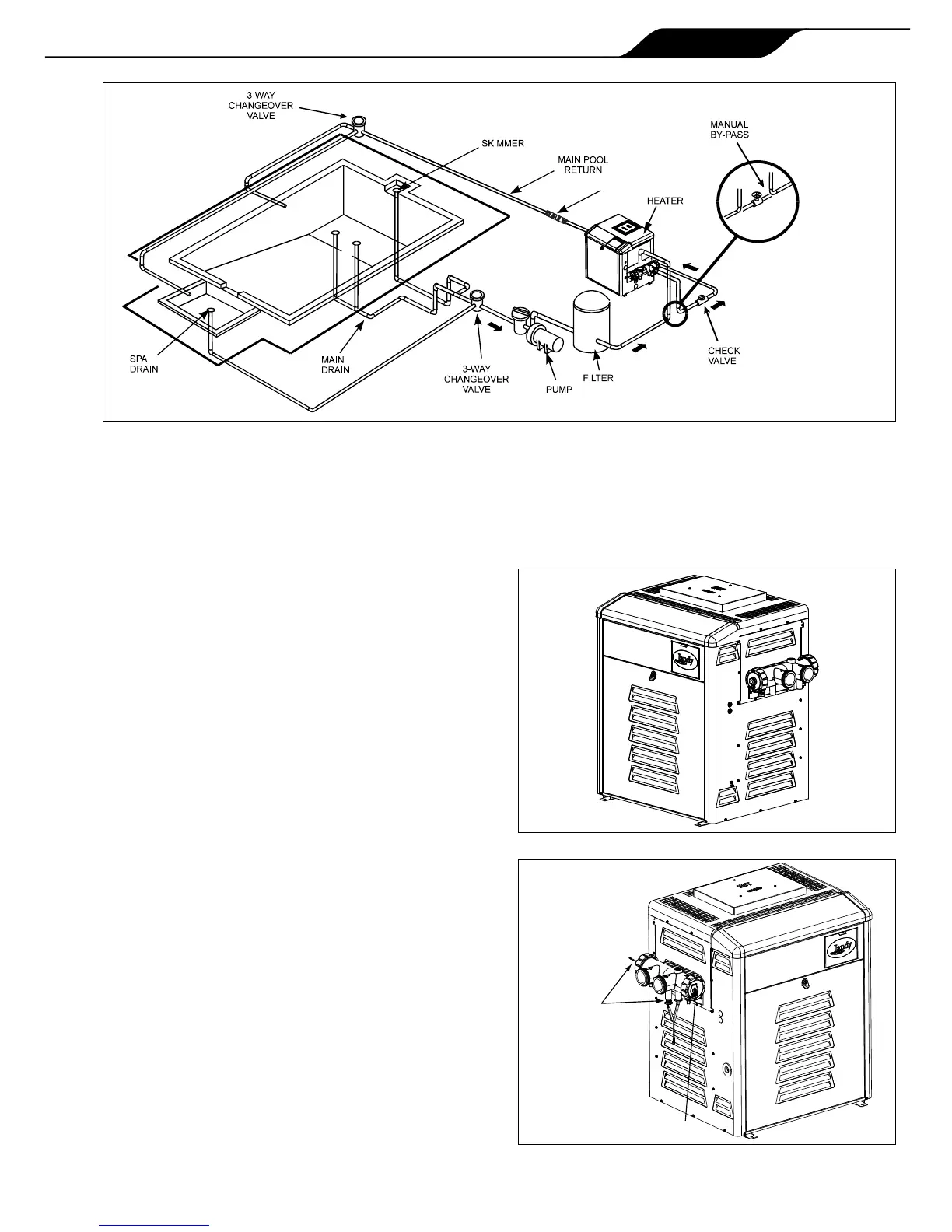
(475 liters per minute [LPM]). If the lter system
ow rate is higher than approximately 125 GPM (475
LPM), install a manual bypass valve, see Figure 7,
then perform a temperature rise test, see Section 7.8
and adjust the ow using the bypass valve until the
proper temperature rise is obtained.
Reversingtheheaderrequiresalonger
syphontube,orderpartnumberR0483601.
The Legacy Model LRZ electronic heater is
shipped with water connections on the right side,
but can be modied in the eld to provide left-side
water connections. This procedure involves removing
the heat exchanger headers and reinstalling them
on opposite ends of the tube assembly. Some of the
heater wiring must be disconnected and re-routed, so
this procedure must be done only by a trained service
technician. Heat exchanger reversals are generally
done before the installation of power and water to the
heater. If you need to reverse the heat exchanger on
a previously installed heater be sure that all electrical
power, the gas supply and water supply have been
turned off before starting the procedure. These
instructions have been written to include the steps
needed when reversing the water connections on an
existing installation. If you are reversing the headers
on a new installation, some steps will be ignored.
Water connection reversal is illustrated in Figures 8
and 9.
AQUAPURE
MANUAL BY-PASS DETAIL
MANUAL BY-PASS IS USED
WHEN FILTRATION RATE
EXCEEDS 125 GPM
NOTE: When reversal
is complete the water
temperature sensor
wires and the syphon
loop tube will exit the
inlet/outlet header at
the back of the heater
and the drain plugs are
facing down.
Bypass