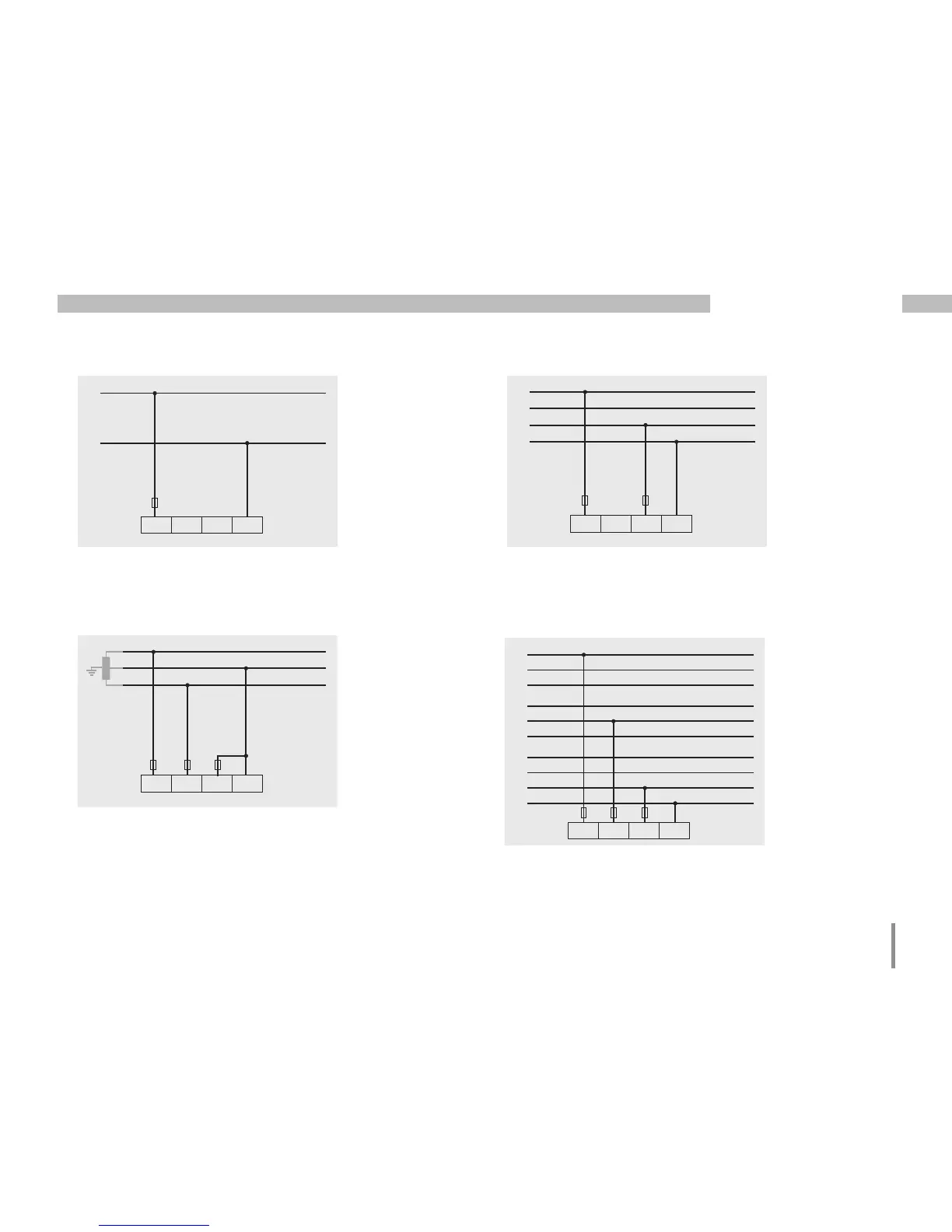
• 1p 2w (addr. 509 = 6)
L1
L2
V1 V2 V3 VN
L1
L2
L3
N
V1 V2 V3 VN
• 2p 4w (addr. 509 = 3)
L1
N
V1 V2 V3 VN
• 1p 2w1 (addr. 509 = 4)
Fig. TN-C system with single-phase, three-wire
connection. Measured values derived from the
V3 voltage measurement input Zero are assu-
med to be zero and not calculated.
Fig. Measured values derived from the V2 and
V3 voltage measurement inputs are assumed to
be zero and not calculated.
Fig. System with uniform phase loading. The
measured values for the V2 voltage measure-
ment input are calculated.
L1
L2
L3
L1
L2
L3
L1
L2
L3
V1 V2 V3 VN
N
• 3p 1w (addr. 509 = 7)
Fig. Three systems with uniform phase loading.
The measurement values L2/L3 resp. L1/L3 resp.
L1/L2 of the respective system are calculated.

 Loading...


