18 of 76
NOTE: THE CYLINDER ROD MUST BE FULLY EXTENDED IN ORDER TO ATTACH
THE NON-THREADED ENDS (SLEEVES) OF THE CABLES TO THE CABLE FLANGE
ON CYLINDER ROD. USE COMPRESSED AIR IN THE SHOP AND AN AIR NOZZLE
AT THE BREATHER END TO EXTEND THE CYLINDER ROD. USE CAUTION AND
PROTECTIVE EQUIPMENT WHEN WORKING WITH COMPRESSED AIR.
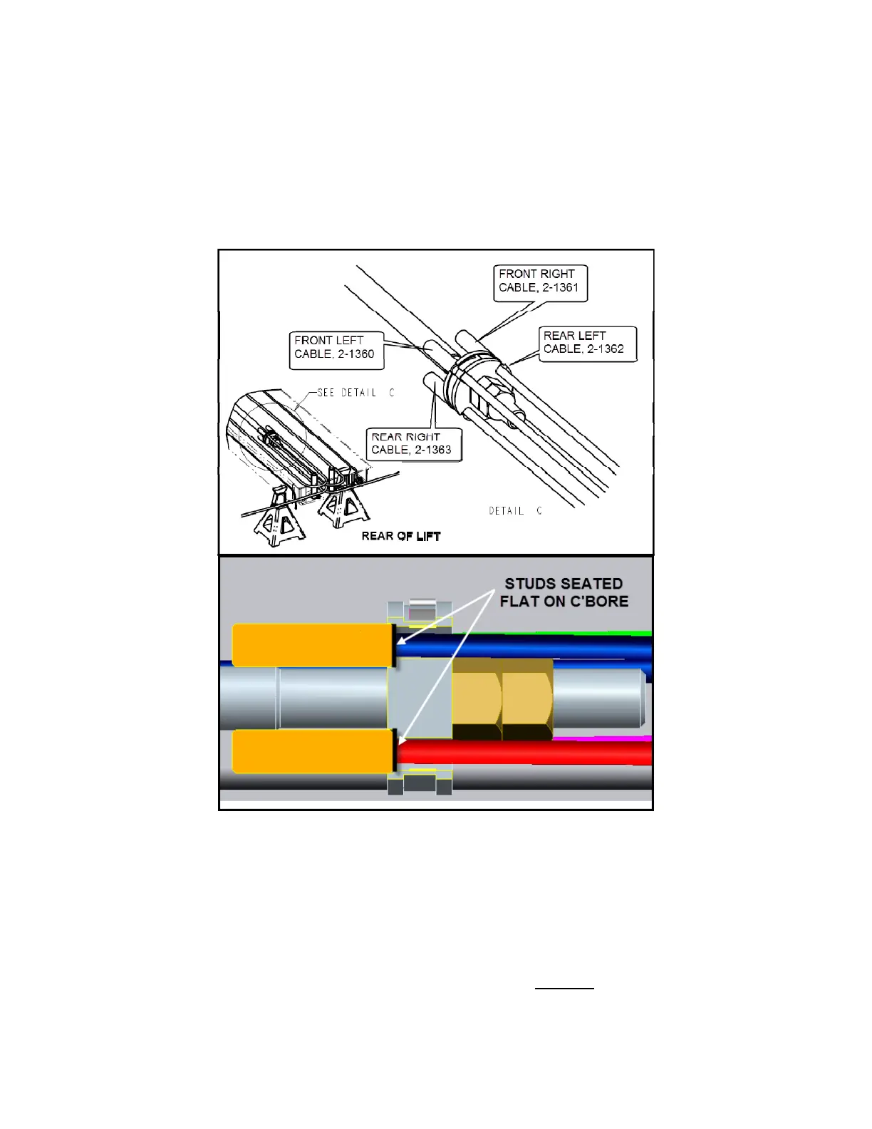
6. Loosen the hose clamp on the cable flange and assemble the studded end of
each cable to the flange as shown in Figure 6. Ensure the cable studs are
seated properly in the counterbore. Tighten the hose clamp.
Figure 6. Cable Flange and Cable Assembly
7. Use Figure 7 as reference during the rear pulley stack and cable assembly.
Each cable will enter the pulley stack in the middle of the runway and wrap
around the pulley 90 degree (for rear) or 180 degrees (for front).
8. Remove the pulley pins and hardware from rear of runway.
9. Referring to Figure 7 and Figure 8, assemble the left side of the pulley stack, as
shown, with cables 2-1363 & 2-1360 starting from the bottom of the stack and
working to the top.