34
5.1.1-1
The wheel must also be tightened securely to prevent
it from slipping in relation to the flange. If the wheel
slips on‘ the balancer, accurate weight measurement
and location are impossible.
5.1.2 Wheel Rotational Errors.
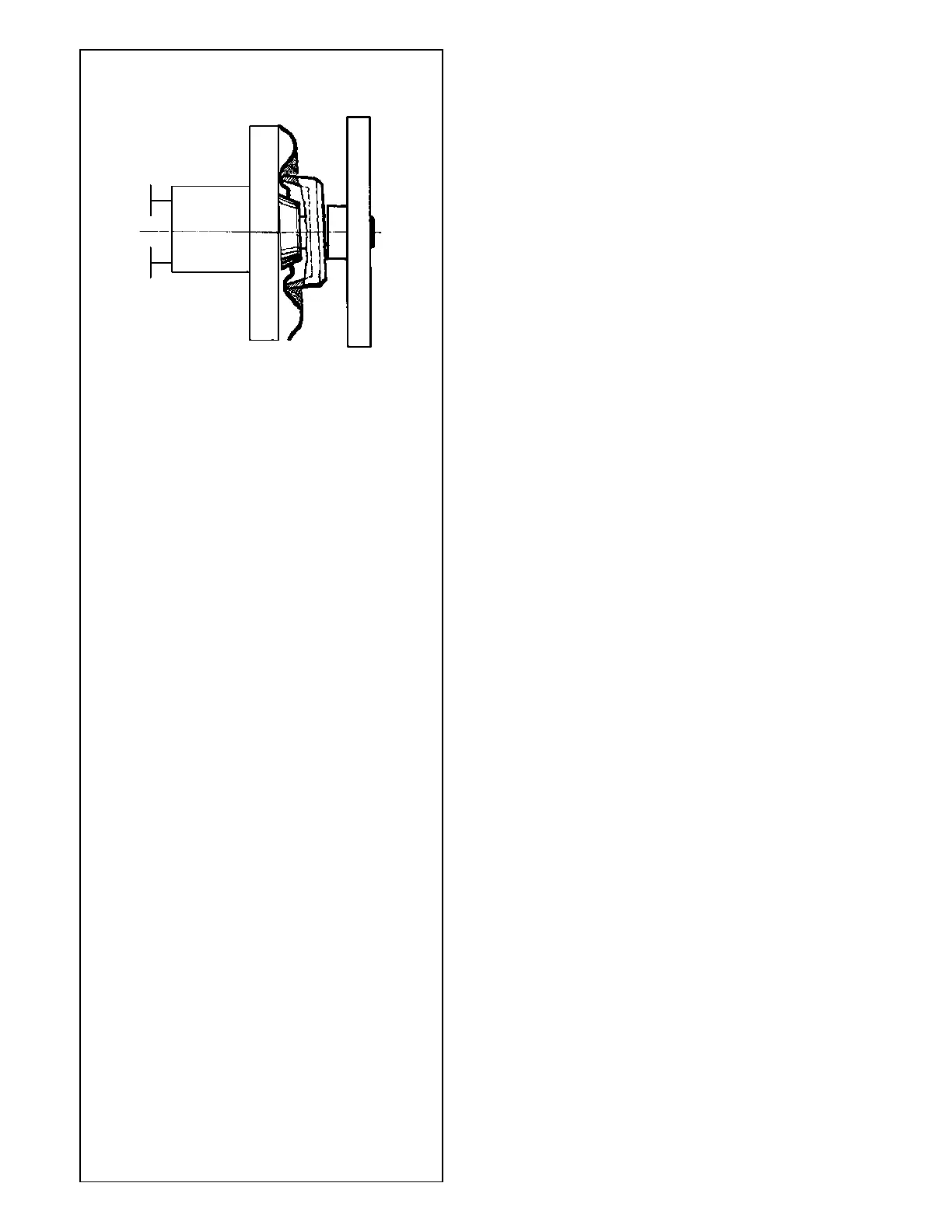
A mounted wheel has a specific position, related to the
balancer shaft reference point.
If the wheel is rotated 180 degrees from the initial
position and re-tightened, a different imbalance reading
may result.
This is caused by mechanical tolerance in the axial
plane and if it happens, it is with hub centric wheels
most of the times. A mechanical tolerance, between
shaft and cone or cone and the wheel center hole, of
0.1 mm may result in an imbalance of 10 gram.
To calculate the rotational error:
• Select a NORMAL weight mode.
• Spin the wheel. Note down the imbalance.
• Rotate the wheel 180 degrees from the initial
position.
• Spin the wheel. Note down the imbalance.
• Subtract the readouts per plane.
The difference between the two readings could be
as much as 15 grams (0.50 ounce) for cone-
mounted automobile wheels and 60 grams (2
ounces) for light truck wheels.
• If the difference is higher, check the shaft, cones
and the centre hole of the rim for wear or damage.
Try different cones and/or rims to determine what
causes the rotational error.
• If the rotational error can not removed, call service.
The actual imbalance error is one-half of the rotational
error.
5.1.3 Removal of the wheel.
• Carefully untighten the quick release hub nut or the
mounting studs.
• Do not slide the rim on the threads, but lift the wheel
when removing it.
• Check the thread for damage and clean if
necessary.
 Loading...


