90
5.5.4.4-3
5.5.4.4-6
5.5.4.4-2
5.5.4.4-5
5.5.4.4-4
• Enter the valve position by pressing menu key F6.
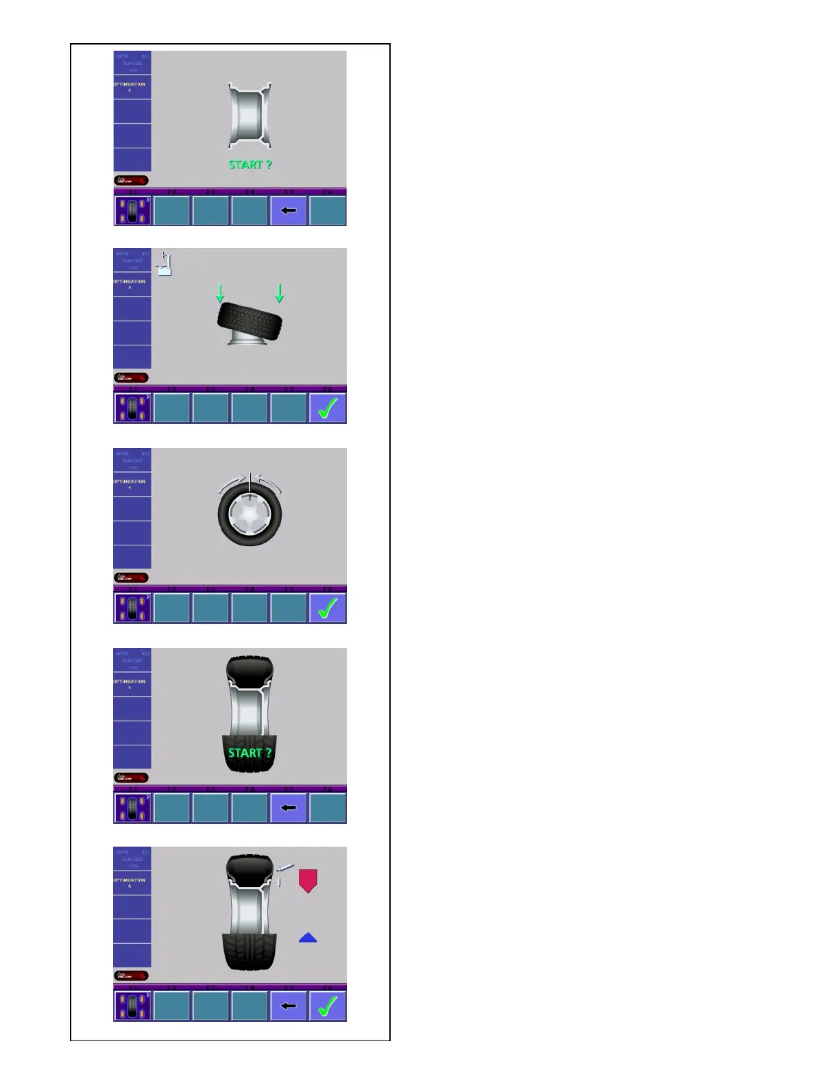
The OPTIMIZATION 1 screen (Fig. 5.5.4.4-2) is
displayed.
Fig. 5.5.4.4-2 OPTIMIZATION 2
START? is signaled on the screen.
• If necessary, go back by pressing menu key F5.
• Press the START key.
A compensation run is performed.
The screen as shown in Fig. 5.5.4.4-3 is displayed.
Fig. 5.5.4.4-3 OPTIMIZATION 3
• Mount the tire correctly on the rim and inflate to
specified inflation pressure (make sure the
mounting guide rim of the tire is correctly seated).
• Confirm by pressing menu key F6.
The OPTIMIZATION 4 screen (Fig. 5.5.4.4-4) is
displayed.
Fig. 5.5.4.4-4 OPTIMIZATION 4
(first measuring run of tire/rim assembly)
• Clamp the wheel on the balancer.
• Readjust the wheel such that the valve is exactly
perpendicular to and above the main shaft.
• Enter the valve position by pressing menu key F6.
The OPTIMIZATION 5 screen (Fig. 5.5.4.4-5) is
displayed.
Fig. 5.5.4.4-5 OPTIMIZATION 5
START? is signaled on the screen.
• If necessary, go back by pressing menu key F5.
• Press the START key.
A measuring run is performed.
The OPTIMIZATION 6 screen (Fig. 5.5.4.4-6) is
displayed.
5.5.4.5 Continue minimization and optimization
Fig. 5.5.4.4-6 OPTIMIZATION 6
(second measuring run of tire/rim assembly)
From this screen weight minimization is carried out in
the same way as optimization.
• Rotate the wheel into marking position following the
arrows.
• Provide a single mark on the tire outer side exactly
perpendicular to and above the main shaft.
• If necessary, go back by pressing menu key F5.
• Confirm by pressing menu key F6
The OPTIMIZATION 7 screen (Fig. 5.5.4.5-1) is
displayed.
Fig. 5.5.4.5-1 OPTIMIZATION 7
• Readjust the tire on the rim such that the single
mark coincides with the valve (use tire changer).
• Confirm by pressing menu key F6.
The OPTIMIZATION 8 screen (Fig. 5.5.4.5-2) is
displayed.
Fig. 5.5.4.5-2 OPTIMIZATION 8
(3rd measuring run of tire/rim assembly)