52
5.3.3.3-1
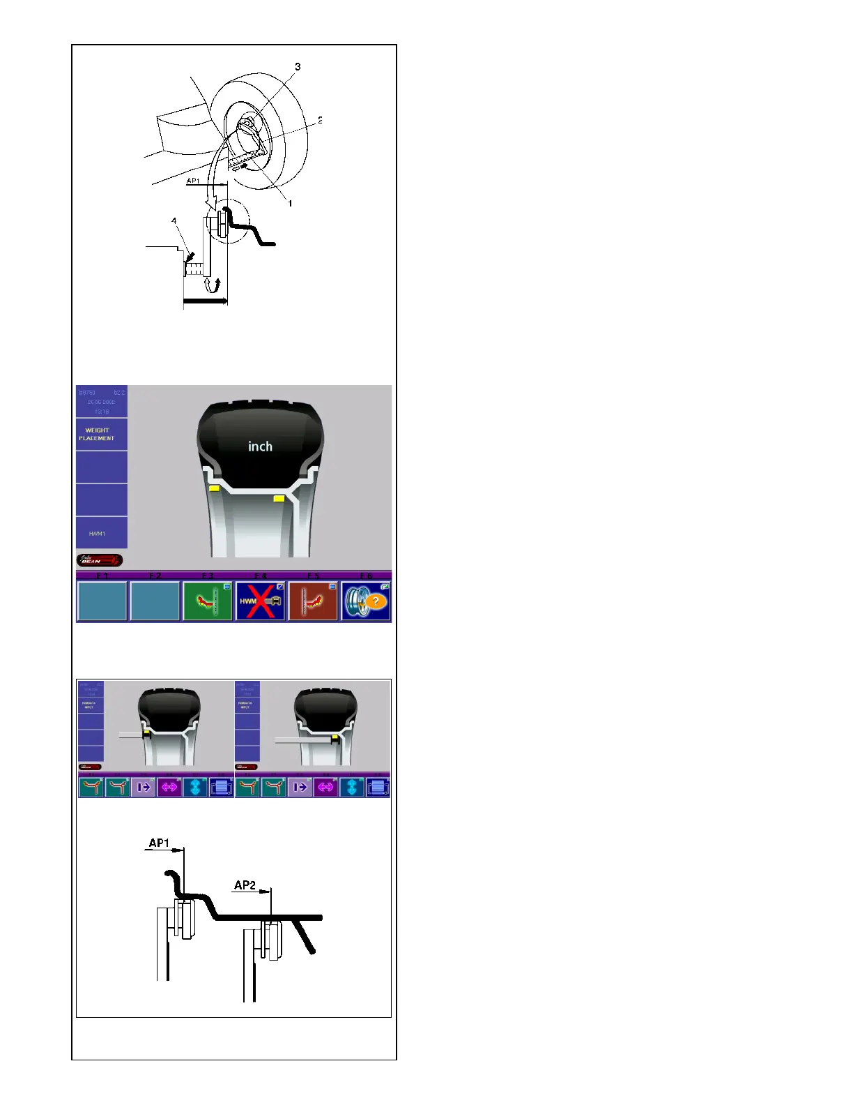
5.3.3.5-1
5.3.3.5-2
5.3.3.5 Determining the position of the hidden
weights (Alu 2S)
Note
Enter nominal rim width before determining the position
of the weights.
• After having selected Alu 2 on the screen WEIGHT
PLACEMENT press menu key F4 to choose
balancing mode Alu 2S.
Alu 2S appears on the screen (Fig. 5.3.3.5-1).
• Return to the screen RIM DATA INPUT by pressing
the ESC key.
Recommendation
Clamp an adhesive weight in the weight holder of the
gauge head with the cover film of the weight being in
top position prior to scanning the correction dimensions.
Fig. 5.3.3.5-2 Scanning of the exact correction
dimensions
a Positioning of the gauge arm for application position
AP1
b Positioning of the gauge arm for application position
AP2
c Exact application position AP1 and AP2
• To determine the gauge application position AP1,
pull the gauge arm for distance and rim diameter
out of the cabinet, apply the gauge head on the
rim in the center of the intended weight fitting
position as shown in Fig. 5.3.3.5-2a and 5.3.3.5-
2c and hold in that position.
An audible signal is given when application position
AP1 has been stored.
• Approach the gauge head to application position
AP2 (Fig. 5.3.3.5-2b and 5.3.3.5-2c) and hold in
that position.
An audible signal is given when application position
AP2 has been stored.
• Return the gauge arm for distance and rim diameter
to its home position.
The rim dimensions are read out on the monitor
between the relative arrows in the display fields as soon
as the gauge arm is moved into its home position after
the measurement.
• Start the measuring run.
Fitting of balance weights
• Select an adhesive weight for AP1 of the indicated
size and adjust it to the wheel radius by bending.
• If necessary, index the wheel precisely into the
correction position for the left plane. When the
correction position is reached, the two arrows on
the screen light up green.
• Press the pedal of the main shaft lock to hold the
wheel in this position.
5.3.3.5-2c
5.3.3.5-2a 5.3.3.5-2b