89
5.5.4.3-3
5.5.4.3-1
5.5.4.3-2
5.5.4.3-5
5.5.4.3-4
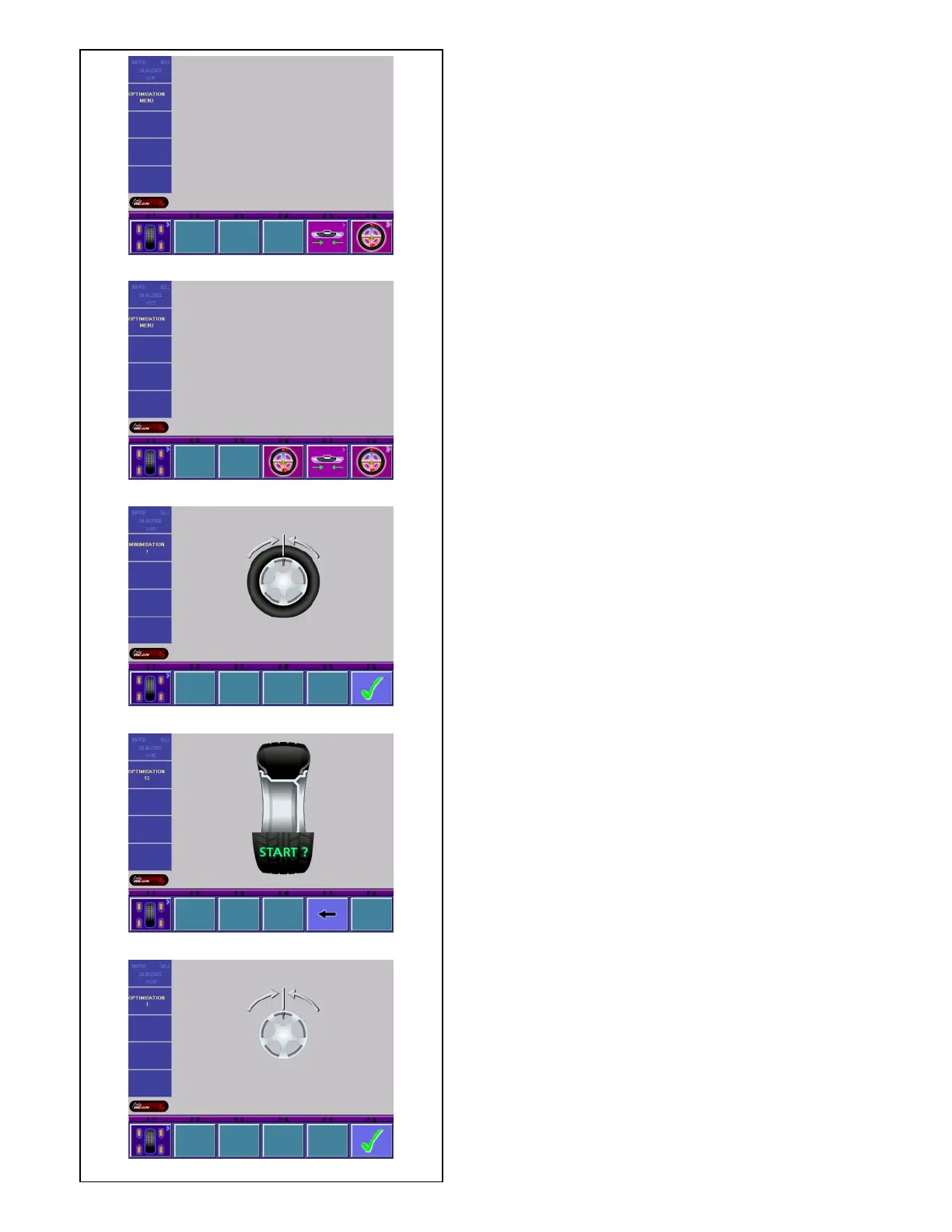
5.5.4.3 Start optimization/weight minimization
• Make sure the tire is correctly mounted on rim and
inflated to specified inflation pressure (mounting
guide rib of the tire must be correctly seated).
• Clamp the wheel.
• Enter correct rim dimensions, or check existing
inputs for correctness.
• Starting from the main menu or the BALANCING
screen press the menu key F6 Optimization menu.
The OPTIMIZATION MENU screen (Fig. 5.5.4.3-1) is
displayed.
If an optimization/weight minimization result has
already been saved, the screen OPTIMIZATION
MENU (Fig. 5.5.4.3-2) will be displayed.
Start weight minimization
• Press the menu key F5.
The MINIMIZATION 1 screen (Fig. 5.5.4.3-3) is
displayed.
Start weight optimization
• Press the menu key F6.
The OPTIMIZATION 1 screen (Fig. 5.5.4.3-5) is
displayed.
Continue optimization or weight minimization
• Press the menu key F4.
The screen in which optimization/weight minimization
was
previously interrupted is displayed.
Fig. 5.5.4.3-3 MINIMIZATION 1
(First measuring run of tire/rim assembly)
• Readjust the wheel such that the valve is exactly
perpendicular to and above the main shaft.
• Enter the valve position by pressing menu key F6.
The MINIMIZATION 2 screen (Fig. 5.5.4.3-4) is
displayed.
Fig. 5.5.4.3-4 MINIMIZATION 2
START? is signaled on the screen.
• If necessary, go back by pressing menu key F5.
• Press the START key.
A measuring run is performed.
• Next proceed as for optimization, starting at the
screen as shown in § 5.5.4.5.
5.5.4.4 Start optimization
• Clamp the rim only on the balancer.
• Enter correct rim dimensions, or check existing
inputs for correctness.
• Starting from the main menu or the BALANCING
screen press the menu key F6 Optimization menu.
The OPTIMIZATION MENU screen (Fig. 5.5.4.3-5) is
displayed.
Fig. 5.5.4.3-5 OPTIMIZATION 1
(Compensation run of rim only)
• Readjust the wheel such that the valve is exactly
perpendicular to and above the main shaft.