91
5.5.4.5-2
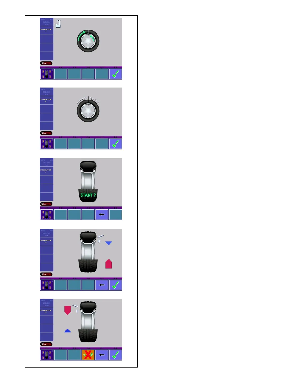
5.5.4.5-5
5.5.4.5-1
5.5.4.5-4
5.5.4.5-3
• Clamp the wheel on the balancer.
• Rotate the wheel such that the valve is exactly
perpendicular to and above the main shaft.
• Enter the valve position by pressing menu key F6.
The OPTIMIZATION 9 screen (Fig. 5.5.4.5-3) is
displayed.
Fig. 5.5.4.5-3 OPTIMIZATION 9
START? is signaled on the screen.
• If necessary, go back by pressing menu key F5.
• Press the START key.
A measuring run is performed.
The screen OPTIMIZATION 10, outside (Fig. 5.5.4.5-
4) or the screen OPTIMIZATION 10, inside (Fig.
5.5.4.5-5) is displayed.
Fig. 5.5.4.5-4 OPTIMIZATION 10, outside
• Rotate the wheel into marking position following the
arrows.
• In this position provide a double mark on the tire
outer side exactly perpendicular to and above the
main shaft.
• If necessary, go back by pressing menu key F5.
• Confirm by pressing menu key F6.
The OPTIMIZATION 11 screen (Fig. 5.5.4.5-6) is
displayed.
Fig. 5.5.4.5-5 OPTIMIZATION 10, inside
• Rotate the wheel into marking position following the
arrows.
• In this position provide a double mark on the inside
of the tire, exactly perpendicular to and above the
main shaft.
• If necessary, go back by pressing menu key F5.
• Confirm by pressing menu key F6.
The OPTIMIZATION 11, turn screen (Fig. 5.5.4.5-7)
is displayed.
Fig. 5.5.4.5-6 OPTIMIZATION 11
• Readjust the tire on the rim such that the double
mark coincides with the valve (use tire changer).
• Confirm by pressing menu key F6.
The OPTIMIZATION 12 screen (Fig. 5.5.4.5-8) is
displayed.
Fig. 5.5.4.5-7 OPTIMIZATION 11, turn
• Turn the tire over on the rim.
• Make the double mark coincide with the valve (use
a tire changer).
• Confirm by pressing menu key F6.
The OPTIMIZATION 12 screen (Fig. 5.5.4.5-8) is
displayed.
Fig. 5.5.4.5-8 OPTIMIZATION 12
(4th measuring run of tire/rim assembly)
• Clamp the wheel on the balancer.
• Rotate the wheel such that the valve is exactly
perpendicular to and above the main shaft.
• Confirm the valve position by pressing menu key
F6.