15
d) The insulated wire of the ribbon cable is put in the slot at the collar of the transducer, with the end protruding about
3-mm over the collar.
e) The plug, with the slot aligned to the wire, is placed upon the collar and then pushed into the collar, to be level with
the edge.
The narrow slot in the terminal strip will cut the insulation and a gas-tight bond is formed between the tinned copper
wire and the contact strip.
A capacitance meter across positions 11 and 12 respectively 15 and 16 of the unplugged connector X6 should read
in the range of 1700 to 2100 pF. The resistance across the same positions and the insulation to the force spreading
members should be more than 109 Ohms.
Service code C75 or a special high-resistance measurement instrument has to be used for the insulation test.
To obtain and keep good insulation, transducers, cable harness and connector X4 have to be kept clean. The collars
should be positioned vertically below the transducers, to keep dust away from the contacts (6-aclock position). To
disconnect the wires, the two plugs have to be removed using a pointed device like a scriber. Insert the scriber in the
slot of the collar just above the wire and lift o• the plug. To pull out the wires, take hold of it at both sides of the collar
to avoid warping of the terminals.
Keep the plugs with the transducer or as spare parts.
As the transducers take pressure forces only, they are clamped into the vibratory assembly under mechanical pre-
load, which is greater than the maximum forces produced by unbalance.
The forces are conveyed via 8-mm balls to the thrust spreading members, so that lateral movement does not
introduce forces on the piezo disc.
ATTENTION! With an already calibrated balancer, twisting the transducers can adversely e• ect plane separation.
3.9 TEMPERATURE SENSOR
The system has a new force guidance structure. The forces at the measuring transducers have been reduced, thus
achieving long-term stability and high measuring accuracy. Pre-tensioning of the transducers is achieved by two
leaf springs. On the vibratory system the measuring transducers are very close together so that the di• erence in
temperature has only a slight e• ect. The current vibratory sensor has a a digital temperature sensor integrated into
the optoencoder. The transducers can therefore be measured by one temperature sensor and taken into account
in a fraction of a second. This temperature sensor e• ects the transducers and is set during calibration. The signal
from temperature sensor is used to the compensate for temperature – dependant force to change conversion of the
unbalance transducers. With a defective sensor, the balancer will stay operational except for temperature correction
of the unbalance amount reading. The actual temperature reading will be substitute by temperature value determined
during calibration. Indication of current temperature is with service code C57.
The signal from temperature sensor is used to compensate for the temperature-dependant force to change conversion
of the unbalance transducers.
3.10 INCREMENTAL ENCODERS
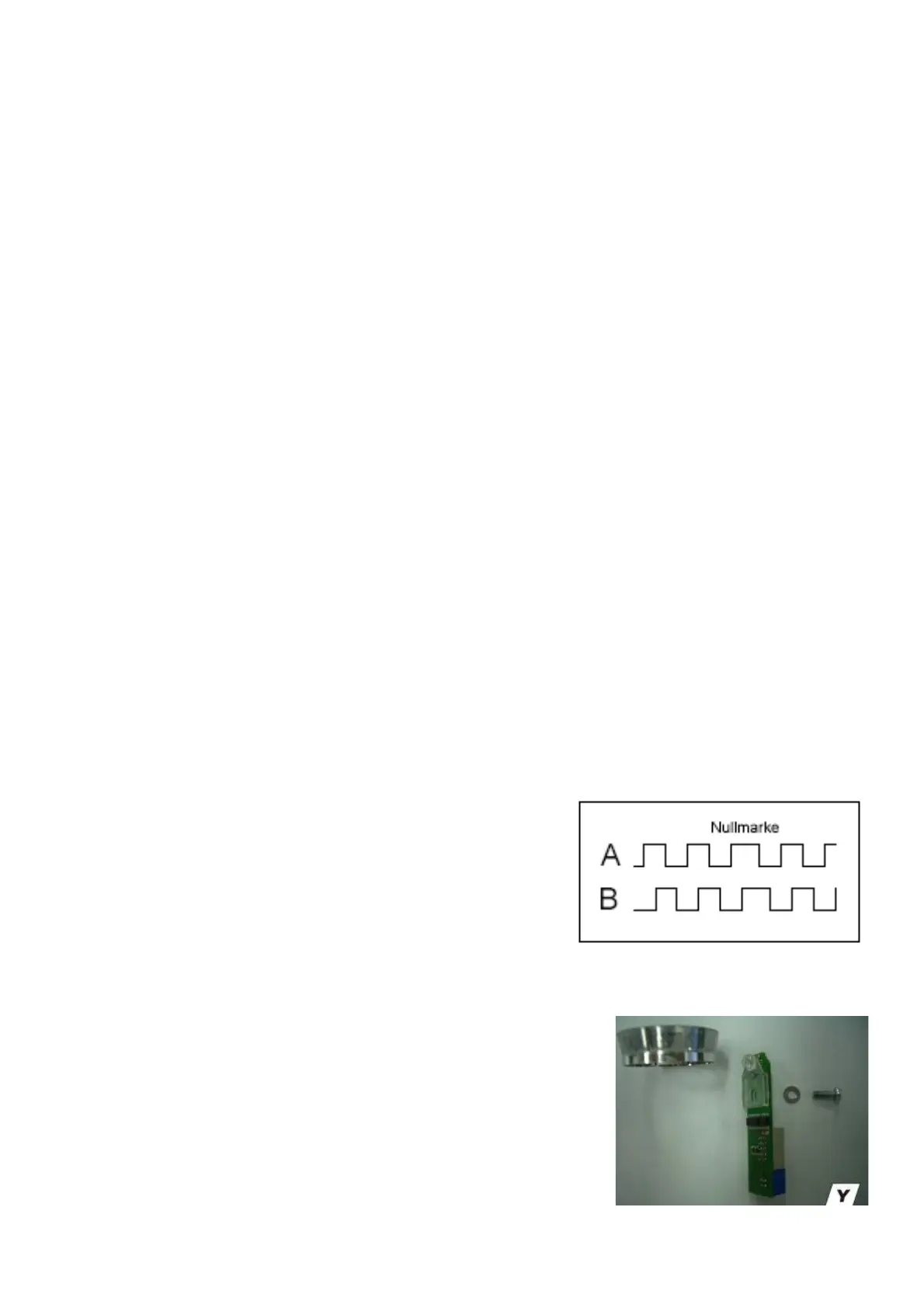
An incremental encoder picks up the rotational travel, direction of rotation,
and absolute angular position of a rotating shaft.
One revolution is divided in increments (periods or intervals).
The output signals A and B have about the shape and relationship shown.
An intended irregularity (Nullmarke) is detected, with the main shaft
rotating at constant speed. On detection of the irregularity, the position
counter is set to zero thus providing absolute angular reference to the
shaft.
3.11 ENCODER BOARD OF THE MAIN SHAFT
The incremental encoder B8 is located between the ball bearings inside the
vibratory tube.
It consists in a plastic polygonal ring with the Printed Circuit Board (PCB) with
lens (see picture Y).
The polygonal ring consists else of an annular polygon mirror at the main shaft
and the optoencoder unit (with lens) fastened with a screw M4, length 10 mm to
the slot in the vibratory tube.
ATTENTION! To keep dust and light out of the tube, the opening for the Optoencoder unit has to be covered with the
dedicated plastic cover. In the encoder IC on the Optoencoder unit, behind a lens there is a red, in the direction of the